

 Hubungi Kami


Injap Rama-rama Pneumatik: Jenis, Prinsip Kerja & Panduan Pemilihan Lengkap

In automated process plants, a valve failure rarely starts as a structural rupture. It starts quietly: a pneumatic actuator stalls halfway through its stroke due to underestimated dynamic slurry torque; an EPDM seat swells and shreds after exposure to trace hydrocarbons; or a lightweight wafer body pinches the disc shut under pipe expansion stress.
For an instrumentation engineer or procurement manager, replacing a failed automated valve is not just about the cost of a replacement unit. It involves unplanned line shutdowns, lost production batches, and hazardous safety risks.
A injap rama-rama pneumatik is one of the most cost-effective and compact quarter-turn automated flow control devices available—provided it is sized, selected, and actuated correctly for the actual process dynamics.
Quick Selection Summary: Engineering Rules of Thumb
- Concentric vs. High Performance: Penggunaan Resilient Seated Concentric Butterfly Valves for clean water, HVAC, and low-pressure air up to 16 bar and 120°C. Upgrade to High-Performance Double Offset Butterfly Valves or Tiga Injap Rama-rama Offset whenever handling steam, hydrocarbons, slurry, or temperatures above 150°C.
- Penggerak Pneumatik Sizing Margin: Always apply a dynamic safety factor to the valve break-torque: add + 20% hingga + 25% for clean liquids, + 30% hingga + 40% for dry air/gas, and + 50% for slurries, scaling media, or dry bulk solids.
- Body Style Selection: Jangan sekali-kali menggunakan wafer-style valve for dead-end pipe service. Specify a Pneumatic Lug Type Butterfly Valve or Pneumatic Flanged Butterfly Valve so downstream piping can be safely dismantled without depressurizing the upstream line.
- Fail-Safe Mode: Always define process failure modes before ordering: Fail-Close (FC) for hazardous fuel and toxic lines; Fail-Open (FO) for cooling water jackets and fire relief loops.
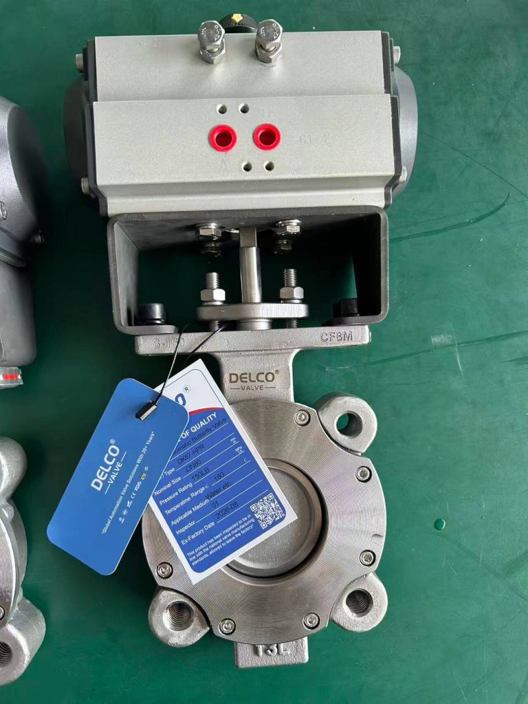
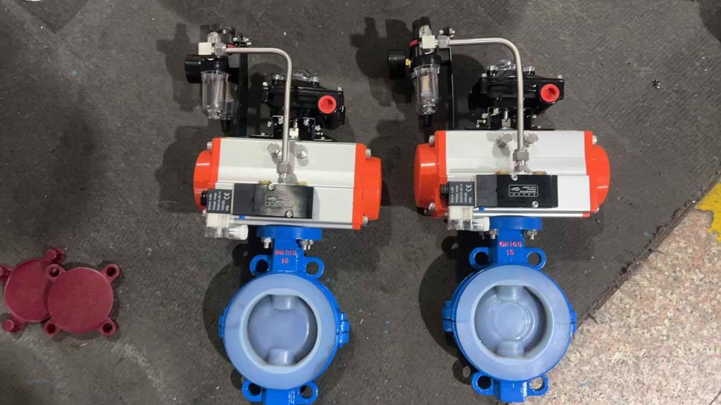
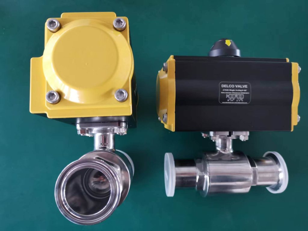
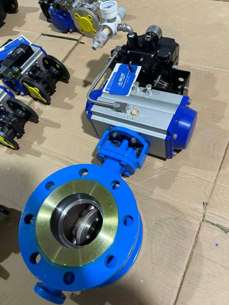
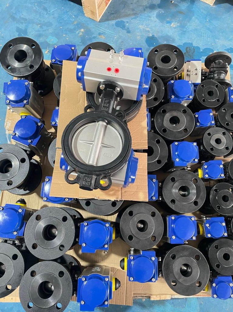
What Is a Pneumatic Butterfly Valve & How Does It Work?
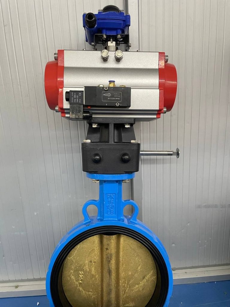
A pneumatic butterfly valve combines a quarter-turn (90-degree) rotational valve with a pneumatic actuator. Compressed instrument air drives internal pistons or a flexible diaphragm, converting linear pneumatic force into rotary torque through a rack-and-pinion or scotch-yoke mechanism to rotate the valve shaft and disc.
The Pneumatic Actuation Process Sequence:

1.Instrument Air Supply (4–7 bar): Clean, regulated plant air enters the control manifold.
2.Signal & Pilot Routing: The solenoid valve or 4–20 mA electro-pneumatic positioner directs air into the actuator chambers.
3.Piston Linear Stroke: Compressed air drives internal dual opposing pistons outward (or spring-assisted inward).
4.Torque Conversion: The internal rack-and-pinion (or scotch yoke) converts linear thrust into 90° rotary torque.
5.Direct Stem Transfer: ISO 5211 direct-mount coupling rotates the valve shaft.
6.Disc Sealing: The disc rotates 0° to 90° for bubble-tight isolation or precision throttling.
The Working Mechanism: Double-Acting vs. Spring-Return
- Double-Acting (DA) Pneumatic Actuation:
- Operasi: Compressed air is supplied to Port A to force the pistons outward (opening the valve). Air supplied to Port B pushes the pistons inward (closing the valve).
- Ciri-ciri: Requires continuous air pressure for both stroke directions.
- Terbaik Untuk: Stable utility lines, large diameter pipelines where spring assemblies would be too bulky, or non-critical loops with secondary air accumulator tanks.
- Single-Acting / Spring-Return (SR) Pneumatic Actuation:
- Operasi: Air pressure drives the pistons against heavy-duty internal steel springs to actuate the valve. When air pressure drops or instrument power fails, the mechanical springs immediately drive the valve to its predetermined fail-safe position.
- Konfigurasi Selamat Gagal:
- Fail-Close (Air-to-Open): Springs close the disc upon signal/pressure loss (standard for isolation and hazardous media lines).
- Fail-Open (Air-to-Close): Springs drive the disc open upon failure (standard for emergency cooling, bypass, and reactor dump systems).
At DELCO Injap, all pneumatic assemblies feature standardized ISO 5211 mounting flanges and NAMUR VDI/VDE 3845 drive dimensions, ensuring seamless pairing with standard industrial limit switches, 4–20 mA electro-pneumatic positioners, and pilot solenoid valves.
Core Valve Types: Concentric, Double Offset, and Triple Offset
Selecting the wrong mechanical disc offset is the number one cause of premature seat wear and actuator overload.
Type 1: Concentric (Resilient Seated) Butterfly Valve
- pembinaan: The stem passes straight through the centerline of the disc and the center of the pipe bore. The disc rim maintains continuous interference contact with the rubber or PTFE liner throughout the full 90-degree travel.
- Mekanisme pengedap: Pure radial mechanical interference.
- Media Ideal: Potable water, raw water, cooling circuits, compressed air, food-grade media, and low-pressure municipal wastewater.
- Had: Not suitable for high temperatures (> 150°C), thermal cycling, or high-cycle throttling due to continuous rubber friction.
Type 2: Double Offset (High-Performance) Butterfly Valve
- pembinaan: The stem axis is shifted behind the plane of the disc sealing surface (Offset 1), and slightly eccentric to the pipeline centerline (Offset 2).
- Operating Benefit: The disc cams off the seat within the first 10 to 15 degrees of rotation. This eliminates sliding contact across the remaining stroke, dramatically reducing operating torque and seal erosion.
- Media Ideal: Low-to-medium pressure steam, hydrocarbons, condensate, vacuum service, and industrial process water up to 260°C.
Type 3: Triple Offset (TOV / Zero Leakage) Butterfly Valve
- pembinaan: Includes Offsets 1 and 2, plus a third offset: the seat cone axis is angled away from the pipeline bore, forming an oblique conical sealing geometry.
- Operating Benefit: 100% friction-free quarter-turn operation. Contact between the laminated metal-graphite seal ring and the metal body seat occurs strictly at the final point of mechanical shutoff.
- Media Ideal: Superheated steam, high-pressure natural gas, corrosive refining streams, hydrogen service, and thermal applications up to 540°C. Provides true bi-directional API 598 / ISO 5208 Rate A fire-safe metal shutoff.
Table 1: Master Technical Comparison – Butterfly Valve Architectures
| Parameter | Concentric (Rubber/PTFE Lined) | Ofset Berganda (Prestasi Tinggi) | Triple Offset (Severe Service) |
|---|---|---|---|
| Julat Tekanan Biasa | PN10 to PN16 (Class 150) | Class 150 to Class 300 (PN25–PN50) | Class 150 to Class 600 (PN20–PN100) |
| Suhu Operasi | -20 ° C hingga + 150 ° C | -40 ° C hingga + 260 ° C | -196°C (Cryo) to +540°C |
| Seat / Seal Type | EPDM, NBR, Viton, PTFE/PFA | Reinforced PTFE (RPTFE), PEEK, Metal | Laminated Metal + Graphite, Stellite weld |
| Keupayaan Tutup | Bubble-tight (Soft seat) | API 598 Bubble-tight | API 598 / ISO 5208 Rate A Metal-to-Metal |
| Friction Across Stroke | Continuous friction 0° to 90° | Friction only during initial 10°–15° | Zero friction until final mechanical wedge |
| Hidup Kitaran | Sederhana | Tinggi (100,000+ kitaran) | Extremely High (Severe thermal cycle) |
| Recommended Body | Injap Rama-rama Wafer Pneumatik | Pneumatic Lug Type Butterfly Valve | Pneumatic Flanged Butterfly Valve |
End Connection Styles: Wafer vs. Lug vs. Flanged
Choosing between body styles is not merely a matter of piping layout—it directly dictates plant safety during pipe maintenance.
| Parameter | Gaya Wafer | Gaya Lug | Double Flanged Style |
|---|---|---|---|
| Reka Bentuk Pemasangan | Clamped between two line flanges with long through-studs | Bolted directly to flanges via threaded peripheral lugs | Independent bolt circles on each side of the valve body |
| Perkhidmatan Buntu | Strictly Prohibited (cannot dismantle downstream pipe) | Fully Capable (downstream line can be safely removed) | Fully Capable (safest choice for pipeline termination) |
| Weight & Footprint | Reka bentuk yang paling ringan dan paling padat | Moderate weight and compact profile | Heaviest design with longer face-to-face dimensions |
| Thermal & Piping Stress | Susceptible to axial pipe compression and distortion | Moderate resistance to pipe expansion and strain | Highest mechanical rigidity; resists heavy pipeline bending loads |
| Julat Saiz Biasa | DN50 hingga DN300 (2" hingga 12") | DN50 hingga DN600 (2" hingga 24") | DN300 to DN2000+ (12" to 80"+) |
| Aplikasi Paling Sesuai | HVAC, compact OEM water skids, non-critical low-pressure lines | Process headers, pump suction/discharge, maintenance-heavy lines | Large water transmission mains, heavy industrial pipelines, marine ballast |
- Gaya Wafer: The valve body is clamped between two line flanges using long continuous studs. It is the lightest and most economical configuration. Amaran Keselamatan: You cannot dismantle downstream pipework without depressurizing and draining the entire system upstream.
- Gaya Lug: Features fully threaded bolt lugs around the body perimeter. Each line flange is secured with independent shorter bolts. This permits dead-end isolation service, allowing downstream maintenance while maintaining full upstream line pressure.
- Gaya Bebibir Berganda: Recommended for larger diameters (DN300 / 12" and above) or heavy-wall structural pipelines. Flanged bodies prevent uneven gasket bolt-load transfer and resist dynamic thermal pipe stress.
Seat & Body Material Compatibility Guide
Corrosive chemicals, abrasive fines, and elevated temperatures degrade valve seats quickly if specified incorrectly. Use this verified compatibility matrix for industrial plant design:
Table 2: Seat Material Compatibility & Engineering Limits
| Bahan Tempat Duduk | Julat Suhu Bekerja | Primary Recommended Media | Strictly Prohibited Media |
|---|---|---|---|
| EPDM | -20 ° C hingga + 120 ° C | Potable water, chilled water, dilute alkalis, low-pressure steam | Hydrocarbons, mineral oils, petroleum greases |
| NBR (Buna-N) | -10 ° C hingga + 82 ° C | Oily wastewater, diesel fuel, lubricated compressed air, hydraulics | Hot water (> 80°C), ozone, strong acids |
| FKM (Viton) | -15 ° C hingga + 200 ° C | High-temp hydrocarbons, synthetic lubricants, chlorinated solvents | Hot water/steam, low molecular esters, ammonia |
| Berlapis PTFE / PFA | -30 ° C hingga + 180 ° C | Concentrated acids, caustic soda, high-purity chemical streams | Molten alkali metals, high-velocity abrasive slurries |
| Stellite / Inconel | -196 ° C hingga + 540 ° C | Superheated steam, hot flue gas, abrasive ash, thermal oil | Low-torque utility service (cost-prohibitive) |
Actuator Torque Calculation & Sizing Rules
One of the most frequent customer inquiries received by the DELCO Injap technical desk is: "Our pneumatic actuator opens smoothly on clean water during commissioning, but stalls after two weeks on the actual production line. Why?"
Actuator sizing cannot rely solely on the factory clean-water bench-test torque. Real pipeline fluid mechanics demand rigorous safety margins.
Total Required Operating Torque = Breakaway Torque × Dynamic Service Safety FactorDynamic Sizing Multipliers
To prevent field stalling, multiply the published valve disc breakaway torque by the following minimum multipliers:
- Clean Lubricating Media (Water, Lubricated Air, Clean Light Oils):
- Pengganda: 1.20 hingga 1.25 (+20% to +25% safety margin)
- Dry, Non-Lubricating Media (Dry Nitrogen, Clean Air, Natural Gas):
- Pengganda: 1.30 hingga 1.40 (+30% to +40% safety margin)
- Viscous or Slurry Fluids (Sludge, Pulp, Lime Slurry, Sugar Syrups):
- Pengganda: 1.50 (+50% safety margin)
- Dry Bulk Solids / Powders (Cement, Lime, Fly Ash, Plastic Pellets):
- Pengganda: 1.60 hingga 1.75 (+60% to +75% margin to overcome seat jamming)
Minimum Air Supply Rule
Pneumatic rack-and-pinion actuators produce torque proportional to the supplied air pressure. Never size an actuator assuming an ideal plant air supply of 7.0 bar if the line pressure regularly drops to 4.5 bar during peak plant operations. DELCO Valve calculates all actuator sizing at the minimum available field air pressure (typically 4.0 or 5.0 bar) to ensure dependable actuation under all conditions.
Table 4: Typical Breakaway Torque & Actuator Sizing Reference (Water @ 10 bar / 20°C)
The table below provides typical bare-shaft breakaway torque values for standard concentric butterfly valves and recommended double-acting (DA) pneumatic actuator torque at 5.0 bar plant air supply (including a 1.30 safety factor):
| Nominal Size (DN / Inch) | Rated Line Pressure | Typical Bare-Shaft Breakaway Torque | Recommended Actuator Output Torque (5.0 bar air) | Recommended ISO 5211 Flange Pattern |
|---|---|---|---|---|
| DN50 (2") | PN16 (16 bar) | 18 Nm | 24–30 Nm | F05 / F07 |
| DN80 (3") | PN16 (16 bar) | 35 Nm | 48–60 Nm | F05 / F07 |
| DN100 (4") | PN16 (16 bar) | 60 Nm | 80–100 Nm | F07 |
| DN150 (6") | PN16 (16 bar) | 130 Nm | 170–200 Nm | F07 / F10 |
| DN200 (8") | PN16 (16 bar) | 260 Nm | 340–400 Nm | F10 / F12 |
| DN250 (10") | PN16 (16 bar) | 450 Nm | 600–700 Nm | F12 |
| DN300 (12") | PN16 (16 bar) | 750 Nm | 980–1150 Nm | F12 / F14 |
Real-World Engineering Failure Teardowns
⚠️ What Goes Wrong in the Field (and How DELCO Prevents It)
Scenario 1: The "Frozen" Disc on Wafer Valves
- Punca Punca: A plant installs an inexpensive Injap Rama-rama Wafer Pneumatik on an unanchored hot water return line. As temperatures fluctuate, piping thermal expansion puts severe axial compressive stress on the valve body. The rubber seat is compressed inward against the disc edge, exceeding the actuator's available output torque.
- The Engineered Countermeasure: On thermal or high-vibration lines, DELCO Injap menyatakan a Pneumatic Lug Type Butterfly Valve or flanged design. The rigid body absorbs pipe tension and compression through external flange bolts, insulating the internal disc-to-seat clearance.
Scenario 2: Rapid Internal Stem Seal Leakage (Fugitive Emissions)
- Punca Punca: Excessive side-loading caused by an off-center actuator bracket or undersized stem bearings under high line differential pressure. The stem flexes microscopically, deforming the O-ring packing and leaking hazardous process media.
- The Engineered Countermeasure: DELCO Injap high-performance and triple-offset units feature precision blow-out proof stems, heavy-duty PTFE/bronze dual guide bushings, and live-loaded Belleville spring packing sets certified to low-emission ISO 15848-1 standards.
Scenario 3: Seat Blowout Under High-Velocity Throttling
- Punca Punca: Operating a conventional concentric butterfly valve partially open (between 15° and 35°) at dynamic fluid velocities exceeding 4.5 m/s. The high differential pressure creates localized cavitation and vacuum suction behind the disc, pulling non-bonded rubber seat liners straight out of their body dovetails.
- The Engineered Countermeasure: For continuous throttling service, DELCO Injap supplies fully vulcanized (bonded-to-body) liners or recommends High-Performance Double Offset Butterfly Valves paired with linear pneumatic positioners to ensure hydrodynamic stability.
Table 3: Valve Troubleshooting & Remediation Guide
| Gejala | Kemungkinan Punca Punca | Field Inspection Point | Engineered Corrective Action |
|---|---|---|---|
| Actuator fails to turn valve | Air pressure drop or under-sized safety factor | Check air gauge at solenoid inlet during stroke | Re-size actuator using 1.3 to 1.5 safety factor at minimum air supply |
| Seat leakage in closed position | Seat abrasion, swelling, or scale deposition | Inspect disc edge and seat face for chemical attack | Replace with chemically compatible seat (e.g., FKM or RPTFE) |
| Jerky / erratic disc motion | Inadequate lubrication or dry media friction | Inspect internal actuator cylinder and rack | Install air line lubricator or fit hard-anodized PTFE-coated actuator body |
| Air exhaust continuously hisses | Damaged internal piston O-ring or solenoid seal | Apply leak-detection spray to actuator vent port | Re-kit actuator piston seals; replace solenoid pilot assembly |
How to Specify Auxiliary Controls & Accessories
A bare automated valve cannot communicate with your distributed control system (DCS) without the right control package.
Automated Control Loop & Signal Architecture:
- 4–20 mA DCS Signal → Electro-Pneumatic Positioner: Precision modulating control (0%–100% linear flow adjustment)
- 24V DC / 220V AC PLC Signal → Solenoid Pilot Valve (NAMUR): Rapid on/off directional air routing (open/close operation)
- Limit Switch Box (SPDT/Inductive Sensors) → Plant PLC: Real-time mechanical open and closed position confirmation
- Instrument Air Supply → Air Filter Regulator (FRL): Conditioned, clean, and regulated moisture-free supply (preset to 4.5–7.0 bar)
- Injap Pandu Solenoid: Direct NAMUR-mount design. Available in 3/2-way (for single-acting spring-return) and 5/2-way (for double-acting). Standard coil voltages: 24V DC, 110V AC, 230V AC with IP65 or ATEX/IECEx explosion-proof enclosures.
- Kotak Suis Had: Provides visual high-visibility position indication and electrical dry-contact feedback (mechanical microswitches or inductive proximity sensors) to the plant PLC.
- Penempatan Elektro-Pneumatik: Required for precise modulating flow control. Converts a 4–20 mA or digital Fieldbus/HART control signal into variable pneumatic output. Includes auto-calibration features.
- Air Filter Regulator (FRL): Essential for removing moisture, rust, and particulate matter from the plant air supply, ensuring a stable operating pressure (typically preset to 5.0 or 6.0 bar).
- Declutchable Manual Gear Override: Mounted directly between the valve and pneumatic actuator. Allows plant technicians to manually operate the valve during plant air outages or emergency maintenance.
EPC Contractor & Distributor Support from DELCO Injap
We understand that for engineering contractors and commercial valve stockists, supplying a valve is about more than just building iron and steel. It requires speed, documentation compliance, and supply chain reliability.
- 12 to 24-Hour Engineering Turnaround: Get complete dimensional GA drawings, wiring diagrams, and formal quotation packages within one business day.
- 100% Factory Acceptance Testing (FAT): Every automated valve assembly is cycle-tested, seat-leak tested according to API 598 / ISO 5208, and verified for stroke calibration before leaving our Dongguan facility.
- Comprehensive Documentation Packages: EN 10204 3.1 Material Test Reports (MTRs), pressure test certificates, CE-PED certifications, ATEX compliance, and paint dry-film thickness (DFT) inspection reports delivered standard with your order.
- Distributor Protection & OEM Solutions: We support global valve distributors with project bidding protection, neutral tagging, laser-etched private branding, and direct container shipping logistics.
Engineering RFQ Checklist
To receive an accurate, optimized quotation without unnecessary technical clarification delays, copy and complete this 7-parameter RFQ template and send it to our engineering team:
Tender Enquiry Parameters:
- Valve Size & Rating: e.g., DN150 (6-Inch), PN16 / Class 150
- Gaya badan: Injap Rama-rama Wafer Pneumatik, Pneumatic Lug Type Butterfly Valve, Atau Pneumatic Flanged Butterfly Valve
- Reka Bentuk Offset: Concentric (Resilient Seated), Double Offset, or Triple Offset
- Bahan Pembinaan: Body (WCB / CF8M / Ductile Iron), Disc (CF8M / Al-Bronze), Seat (EPDM / NBR / PTFE / Metal)
- Process Media & Operating Conditions: Fluid name, concentration, working temperature (°C), maximum working pressure (bar), normal operating flow velocity
- Actuation Parameters:
- Operation: Double-Acting (DA) or Spring-Return (SR)
- Fail Mode: Fail-Close (FC) or Fail-Open (FO)
- Minimum Available Plant Air Supply Pressure (e.g., 5.0 bar)
- Control Accessories: Solenoid valve (voltage/explosion-proof rating), limit switch box, 4–20 mA positioner, manual declutchable gearbox
Soalan-soalan yang kerap ditanya (FAQ)
Q1: Can a pneumatic butterfly valve be used for throttling/modulating flow?
Ya. However, it must be paired with an electro-pneumatic positioner (4–20 mA input) rather than a simple on/off solenoid. For standard concentric valves, throttling should be restricted to disc angles between 20° and 70°. Operating below 20° can cause seat wire-drawing and cavitation; operating above 70° provides negligible additional flow change. For high-velocity modulating loops, specify a Injap Rama-rama Offset Berganda Berprestasi Tinggi to protect the seat seals.
Q2: What is the difference between Wafer and Lug butterfly valves in dead-end service?
A wafer valve cannot be used for dead-end service because it is clamped between two flanges using common through-bolts; removing the downstream flange removes all retention force on the valve body. A Pneumatic Lug Type Butterfly Valve features independent tapped bolt holes on each side. The downstream flange can be removed while the upstream side remains safely pressurized under full design rating.
Q3: Why is my pneumatic actuator torque significantly higher during unseating?
This occurs due to "breakaway torque." When a valve sits closed under line pressure, fluid differential force wedges the disc tightly into the seat. In rubber-lined valves, the elastomer slightly conforms to the disc edge over time, increasing static friction. In metal-seated valves, thermal changes and metal friction create high initial resistance. Once the disc turns 10 to 15 degrees, operating torque drops significantly to normal hydrodynamic dynamic levels.
Q4: How long does a pneumatic butterfly valve take to open or close?
Standard industrial rack-and-pinion actuators typically complete a quarter-turn stroke in 1 hingga 3 saat, depending on actuator volume, line air pressure, and tubing diameter. If faster emergency shutdown (ESD) speeds are required (e.g., under 0.5 seconds), DELCO Injap can integrate quick-exhaust valves (QEV) and high-flow pilot solenoids into the control loop.
Ready to Quote Your Project with DELCO Injap?
Whether you are designing a new chemical processing skid, retrofitting a municipal pumping station, or stocking valves for regional distribution, DELCO Injap delivers precision-engineered automated flow solutions that eliminate line downtime.
- Direct Factory Inquiries: inquiry@delcofluid.com
- Technical Desk & Sales: Contact our application engineering team today for immediate sizing assistance, CAD drawings, and factory-direct pricing.
Kongsi di Sosial:


- SEBELUM: Panduan Pemilihan Injap Rawatan Air: Kebolehpercayaan dan Pematuhan Kejuruteraan
- NEXT: Bukan SETERUSNYA