Motorized Ball Valve: The Complete Guide to Types, Wiring, and Selection
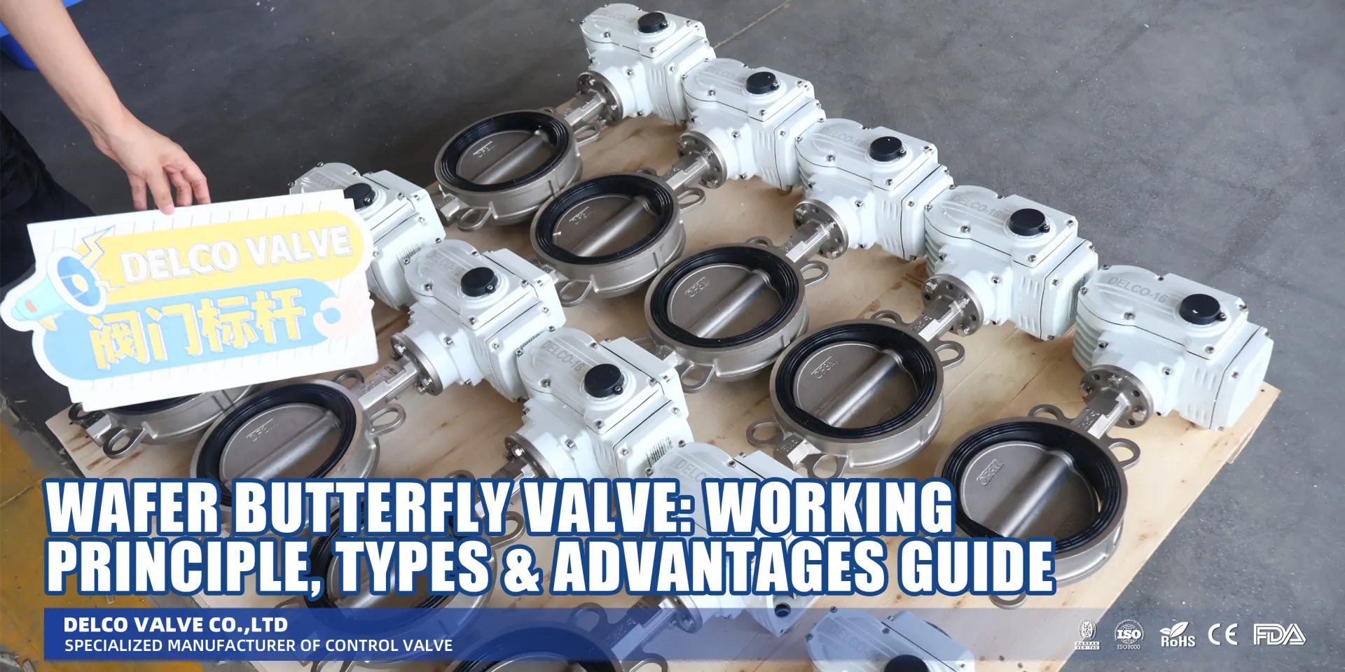
Wafer Butterfly Valve: Working Principle, Types & Advantages Guide
Dec 29, 2025
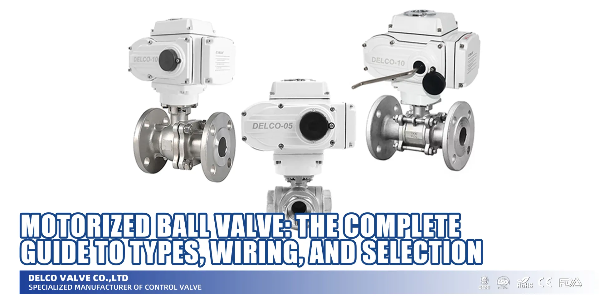
Motorized Ball Valve: The Complete Guide to Types, Wiring, and Selection
Dec 29, 2025
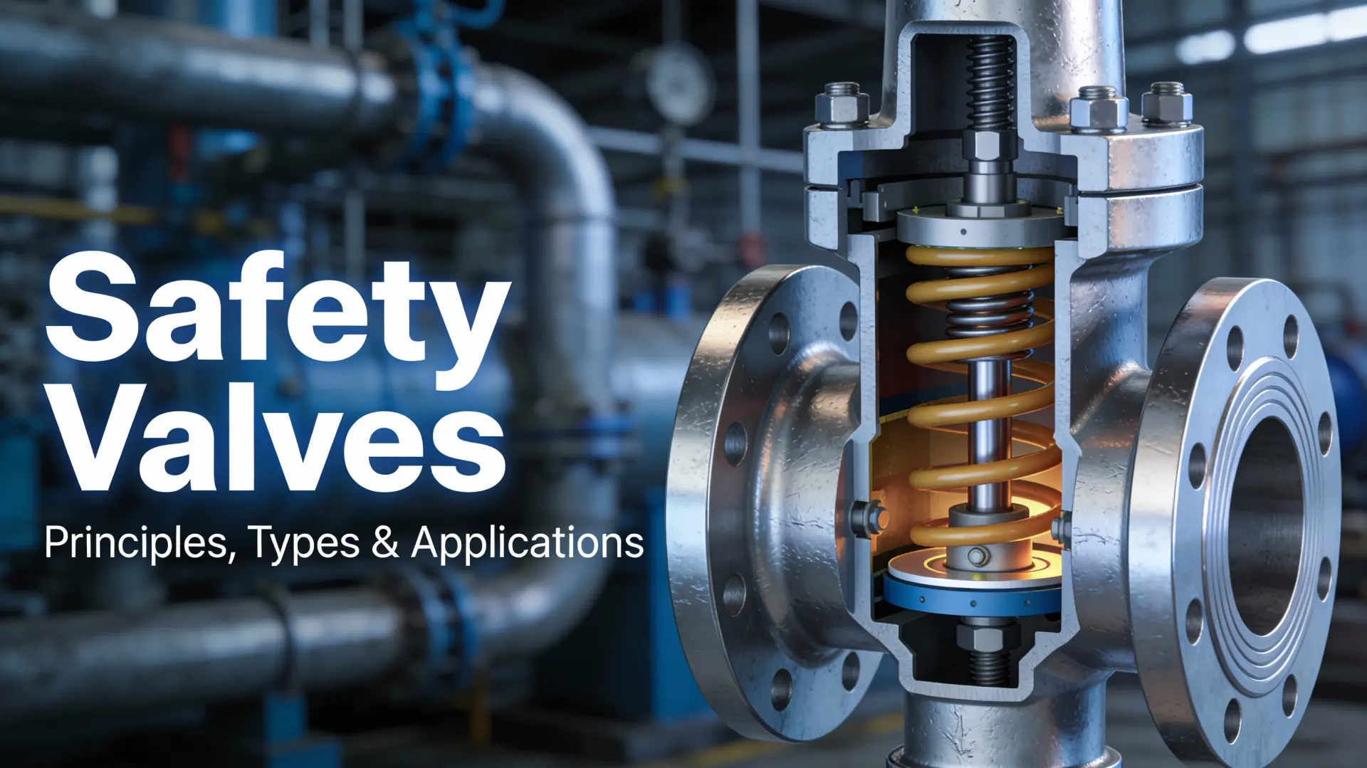
Safety Valves: A Complete Guide to Principles, Types, and Applications
Dec 28, 2025

What Is a Valve: A Complete Guide to Types, Parts, Functions, and Selection
Dec 26, 2025
How Motorized Ball Valves Work
While standard manual valves (see our complete guide on What Is a Valve: Types, Parts, and Functions) require physical effort to operate, a motorized ball valve automates this process using an electric actuator.
Core Components: Under the Hood
To select the right electric actuated ball valve, you first need to know what you are looking at. The assembly generally breaks down into four main critical parts:
- Valve Body: The physical housing (usually Brass, Stainless Steel, or PVC) containing the ball with a hole through it (the bore).
- Electric Actuator: The “muscle” of the unit. This housing protects the motor and electronics.
- Gears: A gear train that reduces the high speed of the electric motor into high torque rating to turn the ball stem slowly and steadily.
- Limit Switches: These are crucial. They cut power to the motor once the valve reaches the fully open or fully closed position, preventing the motor from burning out.
Operating Principle: The 90-Degree Turn
The operation is straightforward but engineered for reliability. When the electric actuator receives a voltage signal (AC or DC), the motor engages.
Through the reduction gears, this rotational energy turns the valve stem exactly 90 degrees. Unlike a solenoid that snaps open, a motorized valve opens gradually (usually 3 to 15 seconds). This controlled movement is vital because it prevents pressure spikes in your piping system. Once the ball rotates the full 90 degrees, the internal limit switch triggers, stopping the motor and holding the valve in place securely.
On/Off vs. Modulating Control
Not all automation needs are the same. In my experience, choosing between simple switching and precise regulation is where most engineers get stuck. Here is the breakdown:
| Feature | On/Off Control | Modulating Control |
|---|---|---|
| Function | Fully Open or Fully Closed only. | Precise flow regulation (e.g., 25% open, 50% open). |
| Signal Type | Simple voltage signal (12V, 24V, 110V). | Analog signal: 4-20mA or 0-10V. |
| Best Use | Filling tanks, emergency shut-off, zone control. | HVAC temperature mixing, precise chemical dosing. |
| Complexity | Low. Easy 2 or 3-wire setup. | Higher. Requires a controller (PLC) and often a position indicator. |
If you just need to stop water, stick to On/Off. If you need to maintain a specific temperature or flow rate, you need a modulating motorized ball valve 4-20mA. This allows the actuator to “listen” to the signal and adjust the ball angle continuously.
Would you like me to help you determine which specific voltage and wiring setup suits your current project requirements?
Types of Motorized Ball Valves
When I look at the market, I see a lot of confusion about which valve goes where. It’s not just about pipe size; it’s about how the valve moves, how it connects to your system, and what it’s made of. To make sure you get the right electric actuated ball valve for your project, I’ve broken down the categories we deal with most often.
Port Configuration: 2-Way vs. 3-Way
This is the most basic physical difference.
- 2-Way Electric Ball Valve: The standard choice for on/off control. It has one inlet and one outlet. It allows flow or shuts it off completely.
- 3-Way Electric Ball Valve: These are used for diverting or mixing flows. You need to pay attention to the ball design here:
- L-Port: Diverts flow from the center port to one of the side ports.
- T-Port: Can connect all three ports for mixing or divert flow like the L-port.
Control Type: From Basic to Precision
How do you want to tell the valve what to do?
- On/Off: Simple open and close.
- Modulating Motorized Ball Valve 4-20mA: This is for when you need precision. Using a 0-10V or 4-20mA signal, you can set the valve to any angle (like 45 degrees) to regulate flow rates exactly.
- Fail-Safe Motorized Ball Valve: These usually have an auto-return function (capacitor or battery). If the power cuts out, the valve automatically returns to a safe position (usually closed) to prevent disaster.
Actuator Wiring Options
Looking at a motorized ball valve wiring diagram can be intimidating if you don’t know the setup. Here is the cheat sheet on how we categorize them:
- 2-Wire: Uses reverse polarity to open and close. Simple and efficient.
- 3-Wire: Uses two distinct control wires (one for open, one for close) and a common wire.
- 5-Wire: Includes position feedback signals so your control system knows exactly where the valve is.
- 7-Wire: Used for high-end modulating valves with complex feedback and heating options.
Materials and Internal Design
We construct valves based on what you are pumping through them.
- Materials: We use Brass for standard water systems, Stainless Steel for corrosive environments or food-grade applications, and PVC for chemical resistance and cost-efficiency.
- Floating vs. Trunnion:
- Floating: The ball is held by the seats. Good for low-to-medium pressure.
- Trunnion: The ball is anchored at the top and bottom. We use this for larger sizes or high-pressure applications to lower the torque requirement.
Next Step: Are you unsure if your system requires a simple 2-wire setup or a modulating feedback loop? Send me your system specs, and I’ll help you select the exact wiring configuration you need.
Motorized Ball Valve vs. Solenoid Valve: Which Is Better?
I see this debate constantly in the field. You’re trying to decide between an electric actuated ball valve and a standard solenoid valve. Both control flow, but they are beasts of different natures.
Choosing the wrong one can lead to burnt coils, water hammer, or just wasted money.
Here is the plain talk on how they stack up so you can make the right call for your system.
Comparing Torque, Speed, and Energy Efficiency
Solenoids are built for speed; motorized ball valves are built for strength and efficiency. Because a motorized ball valve uses a motor to physically turn a ball gear 90 degrees, it handles high pressures and dirty fluids much better than the delicate diaphragm of a solenoid.
Here is a quick breakdown of the key differences:
| Feature | Motorized Ball Valve | Solenoid Valve |
|---|---|---|
| Operation Speed | Slow (5–15 seconds) | Instant (Milliseconds) |
| Water Hammer Risk | Extremely Low | High (due to instant closing) |
| Energy Consumption | Low (Power usually cut after movement) | High (Needs constant power to hold) |
| Flow Rate | High (Full bore available) | Restricted (internal friction) |
| Fluid Compatibility | Handles dirty/viscous fluids well | Prone to clogging |
| Fail-Safe | Requires capacitor or battery | Spring return (standard) |
The “Water Hammer” Factor
This is the biggest deal-breaker for residential and commercial plumbing in the US. When a solenoid snaps shut instantly, it sends a shockwave through your pipes—that’s water hammer. It destroys pipes and fittings over time.
Because an electric ball valve takes a few seconds to close, it naturally dampens that shock. If you are running high pressure in a home or facility, I almost always recommend the motorized route to save your plumbing.
When to Choose an Electric Actuated Ball Valve
While solenoids are great for small, clean lines where you need instant on/off action (like a misting system), you should switch to a motorized ball valve in these scenarios:
- You need Modulating Control: If you need to regulate flow (say, 50% open) rather than just on/off, you need a modulating motorized ball valve 4-20mA or 0-10V. Solenoids can’t do this.
- Large Pipe Diameters: Once you get above 1 inch, solenoids get massive, expensive, and loud. Motorized valves remain compact.
- Dirty Media: If your fluid has rust or particles, a solenoid pilot hole will clog instantly. The high torque rating of a ball valve powers right through the grit.
- Energy Savings matter: If the valve stays open for hours at a time, a solenoid coil will get hot and chew through electricity. A motorized valve uses zero energy once it reaches the open position.
Would you like me to help you calculate the specific torque requirements for your next installation?
Key Selection Criteria: The DAMPT Rule & Advanced Tips
Selecting the right electric actuated ball valve isn’t just about picking a size; it’s about matching the specs to your specific system. I always tell my customers to follow the DAMPT Rule (Diameter, Application, Medium, Pressure, Temperature) to avoid costly replacements later. Here is how we break it down.
Diameter, Connection, and Fluid Compatibility
First, get the sizing right. For the US market, you are usually looking at NPT threads for a secure seal.
- Diameter: Ensure the valve size matches your piping. If flow restriction is a concern, I always recommend a full bore motorized ball valve over a standard port to keep pressure drops low.
- Medium Analysis: What’s flowing through the line? For standard water or HVAC, brass is great. If you are handling corrosive chemicals or food-grade liquids, stick to Stainless Steel (SS304 or SS316).
- Pressure & Temp: Check your system’s max PSI and temperature. Never underspec this—if your line hits 150 PSI, get a valve rated for at least 200 PSI to be safe.
Calculating Torque and Environmental Protection
The motor needs enough muscle to turn the ball, especially after sitting idle.
- Torque Rating: We calculate the motorized ball valve torque rating with a safety factor of at least 30%. If the valve is sticky from debris, a weak actuator will stall or burn out.
- NEMA/IP Ratings: Where is the valve installed? If it is outside or in a damp basement, you need an IP67 motorized ball valve. This rating ensures it is dust-tight and can handle temporary immersion in water.
Voltage Selection: AC vs. DC
Your power source dictates your valve choice. Don’t mix these up.
- 12V/24V DC Motorized Ball Valve: Best for automotive, RVs, solar setups, or automated irrigation systems where safety voltage is preferred.
- AC 110V/220V Motorized Ball Valve: The standard for residential and industrial mains power. In the US, 110V is your go-to for general HVAC and home automation.
Fail-Safe Features: Capacitor vs. Battery
What happens when the power cuts out? This is critical for preventing floods or overheating.
- Fail-Safe Capacitor: I highly recommend fail-safe motorized ball valves with supercapacitors. They automatically return the valve to a preset position (open or closed) during a power loss.
- Battery Backup: While options exist, capacitors are more reliable than batteries, which degrade over time and require maintenance.
Note that while fail-safe motorized valves provide emergency shut-off, they are not a substitute for pressure protection devices. For system overpressure safety, always install dedicated Safety Valves
Would you like me to create a quick wiring diagram comparison for 2-wire vs. 3-wire setups next?
Wiring a Motorized Ball Valve: Step-by-Step Guide
Wiring an electric actuated ball valve shouldn’t be a guessing game. Get it right, and you have a reliable system for years; get it wrong, and you’re looking at a burnt-out board or a valve that just sits there. Since I’ve handled countless installations, I’m going to walk you through the logic we use to get these up and running safely.
Essential Safety and Tools
Before we even look at a motorized ball valve wiring diagram, let’s talk safety. You are dealing with electricity—whether it’s low voltage DC or high voltage AC, safety is non-negotiable.
- Kill the Power: Never wire a live actuator. Lockout/tagout at the breaker.
- Check Voltage: Double-check your actuator’s label. Wiring a 12V/24V DC motorized ball valve to a 110V line will destroy it instantly.
- The Gear: You’ll need a reliable multimeter, wire strippers, small flathead screwdrivers (for terminal blocks), and heat shrink or wire nuts.
Common Wiring Schematics Explained
Different actuators use different control schemes. Here is the breakdown of the most common setups I see in the US market.
2-Wire Setup (Auto-Return or Reverse Polarity)
This is usually found in fail-safe motorized ball valves.
- Power Open/Spring Close: You connect power to open the valve. When power is cut, an internal capacitor or spring forces the valve shut.
- Reverse Polarity: You simply swap the positive and negative poles to change direction.
- Red: Positive (+) to Open, Negative (-) to Close.
- Black: Negative (-) to Open, Positive (+) to Close.
3-Wire Setup (Control Point)
This is the industry standard for many HVAC and water systems. It gives you precise control without needing constant power to hold a position.
- Common (Yellow/Green or Black): Connected to Neutral (AC) or Negative (DC).
- Open Wire (Red): Connect to Live/Hot to open the valve.
- Close Wire (Blue/Green): Connect to Live/Hot to close the valve.
- Note: The limit switch inside cuts the power automatically once it hits 90 degrees, so the motor doesn’t overheat.
5-Wire Setup (With Feedback)
If you need to know the valve’s status remotely, you want a 5-wire setup. It operates like the 3-wire version but adds two extra wires for signal feedback (Open signal/Close signal). This connects to a position indicator on your control panel so you aren’t flying blind.
Voltage Specifics: AC vs. DC
The physical wiring is similar, but the power source demands attention.
- 12V/24V DC Motorized Ball Valve: Polarity matters for DC motors unless the board has a built-in rectifier. Always double-check your Positive (+) and Negative (-).
- AC 110V/220V Motorized Ball Valve: Here, you are dealing with Line (L) and Neutral (N). Ensure your grounding is solid. For AC 220V motorized ball valves, verify if your site uses single-phase or three-phase power, though most small actuators are single-phase.
Integrating Control Signals (Modulating Valves)
For precision flow control, simple on/off switches won’t cut it. You need a modulating electric ball valve 4-20mA or 0-10V.
- Power Wires: Connect constant power (DC or AC) to the actuator.
- Signal Wires: Connect the control signal wires to your PLC or controller.
- 4mA (or 0V): Valve Fully Closed.
- 20mA (or 10V): Valve Fully Open.
- Calibration: Most of our units auto-calibrate, but always cycle the valve fully once after wiring to let the system learn the end stops.
Troubleshooting Wiring Issues
If the valve isn’t behaving, it’s usually a simple fix.
| Symptom | Check This First |
|---|---|
| Valve won’t move | Check power with a multimeter. Is voltage reaching the terminal? |
| Moves in wrong direction | For DC 2-wire, swap polarity. For 3-wire, swap Open/Close wires. |
| Humming but no rotation | Check for debris in the valve body or insufficient torque. Use the manual override to test physical movement. |
| No Feedback Signal | Verify the auxiliary switch wiring is connected to the PLC inputs correctly. |
Next Step: Are you unsure which wiring diagram matches your specific control system? Send me your controller specs, and I can confirm the exact wiring configuration you need.
Electric Ball Valve Installation Best Practices
Getting the electric ball valve installation right is just as critical as buying the right unit. Even the best IP67 motorized ball valve will fail if installed incorrectly. Here is how I ensure a setup that lasts.
Actuator Positioning and Environment
Gravity is your enemy here. Never install the valve with the electric actuator hanging below the pipe. If a seal weeps or condensation forms, water will drip straight into the electronics.
- Best Position: Vertically upright.
- Acceptable: Up to a 45-degree angle.
- Avoid: Upside down (actuator below the valve body).
Piping Alignment and Filtration
Debris is the number one killer of a full bore motorized ball valve. A small rock or metal shaving can score the ball or jam the gears.
- Install a Strainer: Always place a Y-strainer or mesh filter upstream to catch particles.
- Check Alignment: Ensure your pipes align perfectly before tightening. Forcing the valve into place creates stress on the valve body, leading to cracks and leaks later.
Mounting and Torque Specifications
When tightening the valve into the pipeline, never apply torque to the actuator housing. The plastic or aluminum box isn’t designed to handle pipe-wrench force.
- Wrench the Body: Always grip the metal valve body (brass or stainless steel) with your tool.
- Mind the Gap: If you are using a flange type, tighten bolts in a star pattern to distribute pressure evenly.
Testing and Calibration Procedures
Before you fully pressurize the system, run a dry cycle.
- Power Up: Connect the 12V/24V DC or AC power source.
- Cycle the Valve: Use the control switch to open and close the valve fully. Watch the position indicator to ensure it travels the full 90 degrees.
- Manual Check: If power isn’t ready, use the manual override (if equipped) to verify the ball moves freely without binding.
- Leak Test: Once pressurized, inspect connections for any weeping.
Pro Tip: If you are using a modulating electric ball valve (4-20mA), this is the time to calibrate your zero and span settings with your controller to ensure precise flow control.
Would you like me to explain the specific maintenance schedule to prevent motor burnout in the next section?
Maintenance and Troubleshooting for Motorized Ball Valves
You’ve installed a high-quality electric actuated ball valve, but you can’t just set it and forget it forever. To get the best ROI and avoid downtime in your system, a little preventative maintenance is non-negotiable. Whether you are running a water treatment plant or a commercial HVAC setup, keeping these valves in top shape is easier than you think.
Routine Checks: What to Look For
I recommend running a quick inspection schedule at least once every few months. Here is the checklist we use to ensure everything is running smoothly:
- Wiring Integrity: Check your connections. Loose or corroded wires are the #1 cause of intermittent signal failure. Ensure the motorized ball valve wiring is secure and protected from moisture.
- Seal Inspection: Look for any signs of weeping or moisture around the valve stem. This is often the first sign that the internal seals are wearing out.
- Torque Verification: Listen to the motor. If it sounds like it is straining, debris might be trapped in the valve body, or the torque rating might be insufficient for the current pressure.
- Visual Indicators: Verify that the position indicator on top of the actuator matches the actual position of the valve (open vs. closed).
Solving Common Problems
When things go wrong, you need to troubleshoot fast. Here is a quick breakdown of common issues I see in the field and how to fix them:
| Problem | Likely Cause | Quick Fix |
|---|---|---|
| Motor Burnout | Overheating or incorrect voltage | Check if you are feeding AC power to a DC motor. Verify the voltage matches the label (e.g., 12V/24V DC vs. AC 220V). |
| Valve Stuck | Debris or sediment build-up | Cut the power and use the manual override to physically turn the valve back and forth to clear the obstruction. |
| Signal Failure | Loose connection or bad switch | Test the limit switch signals with a multimeter. If using a modulating electric ball valve, check the 4-20mA source. |
| Internal Leaking | Worn ball seats | If the valve is fully closed but flow continues, the seats are damaged. You likely need a replacement or a rebuild kit. |
Extending Lifespan and Protection
To get the maximum life out of your motorized ball valve, environment is everything. Even if your unit has IP67 protection (which makes it dust-tight and water-resistant), you should still avoid mounting it where water pools directly on the actuator.
- Lubrication: Most modern electric actuators are permanently lubricated, but the valve stem might need food-grade silicone grease depending on the medium.
- Cycle the Valve: If a valve sits in one position for months, the seals can stick. Cycle the valve fully open and closed occasionally to keep the movement free.
- Voltage Protection: Install a surge protector if your facility has unstable power to protect the internal capacitor and motor.
Would you like me to create a comparison table for the next section showing why DELCO VALVE outweighs standard competitors?
Why Choose DELCO VALVE Motorized Ball Valves?
When you are looking for a reliable motorized ball valve, you don’t want to second-guess the quality. At DELCO VALVE, we build our valves to handle the gritty demands of the US industrial and residential markets. Whether you need a standard setup or a specific electric actuated ball valve configuration, we focus on durability and ease of use.
We don’t just sell off-the-shelf parts; we provide solutions that solve actual flow control headaches. Here is why our valves stand out:
Key Features That Matter
We engineered our valves to address the common failure points I see in cheaper alternatives.
- High Torque Rating: Our motors pack a punch. They are designed to cut through buildup and handle pressure drops without stalling.
- IP67 Protection: Moisture is the enemy of electronics. Our IP67 motorized ball valve housing ensures dust and water stay out, making them safe for damp basements or outdoor irrigation.
- Manual Override: Power outage? No problem. We include a manual override so you can operate the valve by hand when electricity fails.
- Visual Position Indicators: You shouldn’t have to guess if a valve is open or closed. Our clear indicators give you immediate visual confirmation.
- Full Bore Design: We prioritize flow efficiency. Our full bore motorized ball valves minimize pressure drop compared to standard port options.
Customization and Decision Matrix
Every project is different. That is why we offer a range of options to fit your specific control system, from 12V/24V DC for mobile rigs to AC 220V for heavy industrial lines.
| Feature | Standard Competitor | DELCO VALVE Solution |
|---|---|---|
| Sealing | Basic IP54 | IP67 Protection (Waterproof) |
| Safety | None | Fail-safe capacitor & Manual Override |
| Control | On/Off only | On/Off + Modulating (4-20mA) Options |
| Gears | Plastic | Heavy-duty Metal Gears |
Real-World Performance in HVAC and Water Systems
I have seen our valves deployed across the country, from managing zoning in complex HVAC systems to controlling flow in municipal water treatment plants. Because we use robust sealing and high-quality materials like stainless steel and brass, our valves resist the “water hammer” effect that often kills solenoid valves.
Whether you are retrofitting an old boiler system or building a new automation line, choosing DELCO VALVE means choosing peace of mind.
Would you like me to help you select the exact voltage and wiring configuration for your next project?
Related Sources
Share on Social:
Contact Us
In This Article
Wafer Butterfly Valve: Working Principle, Types & Advantages Guide
Dec 29, 2025
Motorized Ball Valve: The Complete Guide to Types, Wiring, and Selection
Dec 29, 2025
Safety Valves: A Complete Guide to Principles, Types, and Applications
Dec 28, 2025
What Is a Valve: A Complete Guide to Types, Parts, Functions, and Selection
Dec 26, 2025