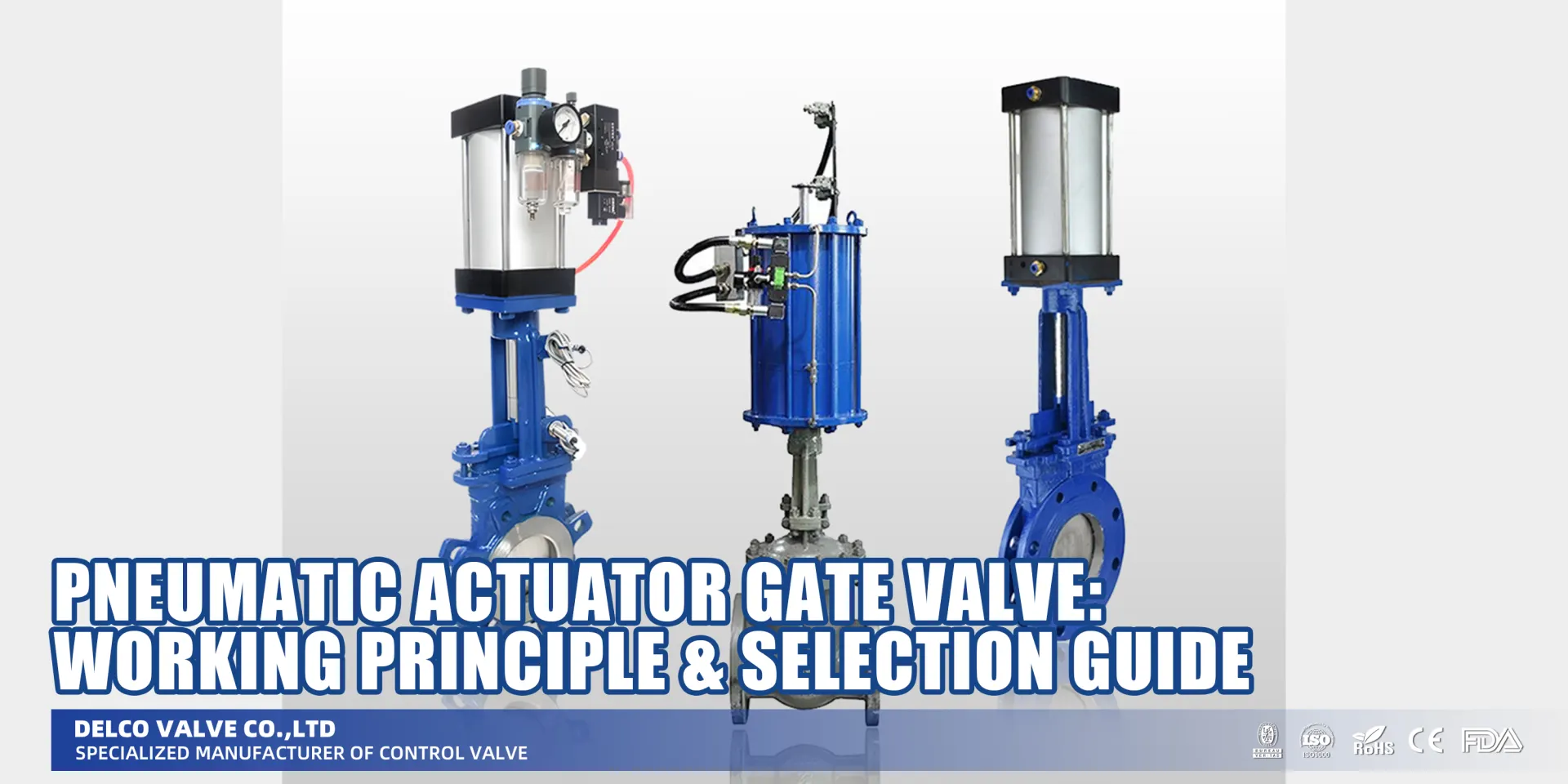
Pneumatic Actuator Gate Valve: Working Principle & Selection Guide
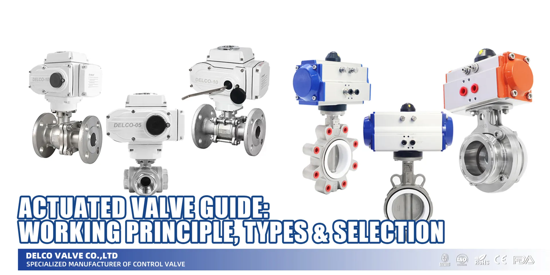
Master the pneumatic actuator gate valve working principle. Discover key benefits, industrial applications, and selection tips in our expert guide.
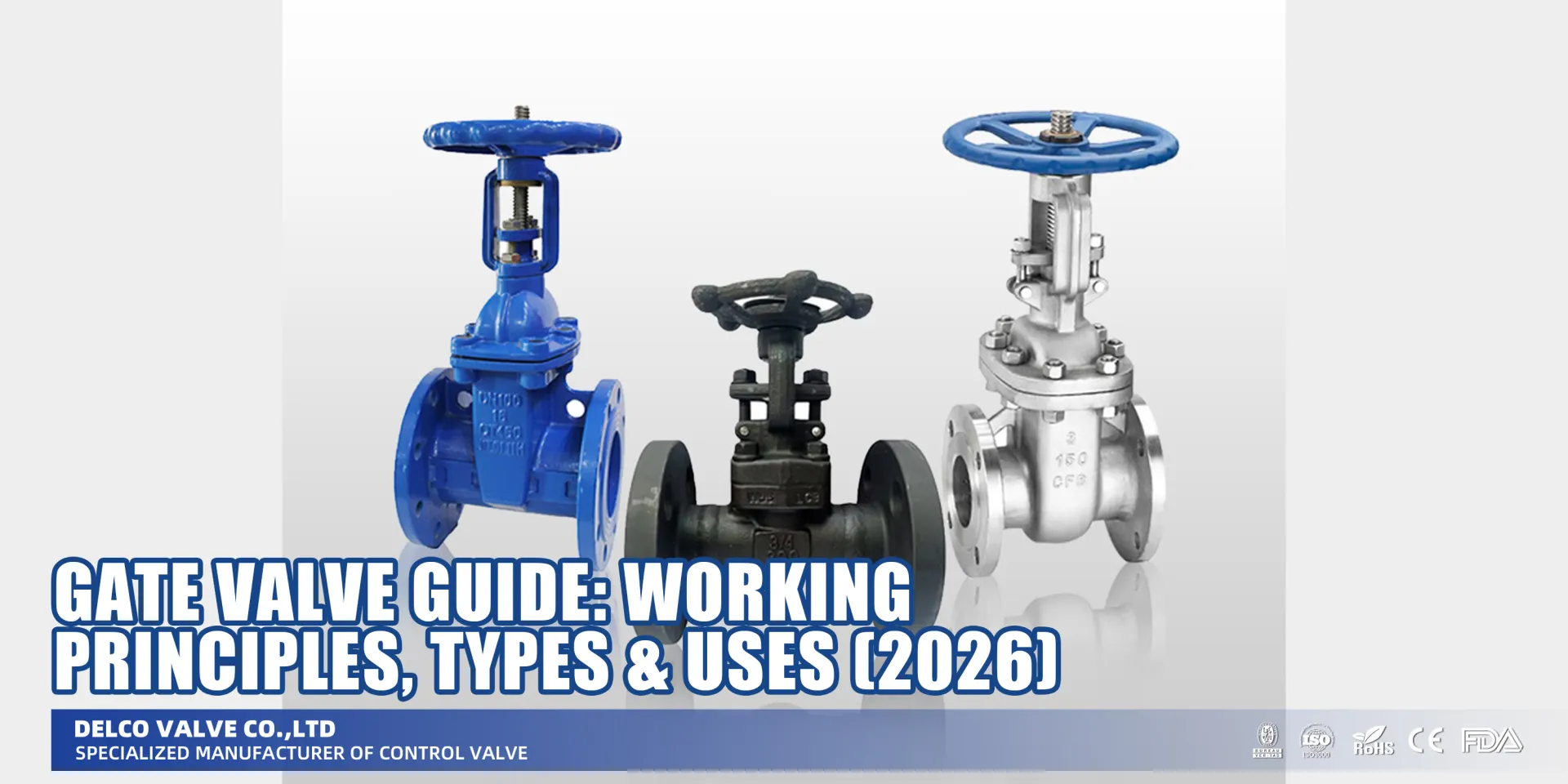
What is a Pneumatic Actuator Gate Valve?
Are you tired of manually cranking large valves or worrying about slow shut-off times in critical emergencies? That is exactly where the Pneumatic Actuator Gate Valve steps in to automate and secure your workflow. Simply put, this is a standard industrial Gate Valve married to a powerful air-operated cylinder. While the valve body handles the isolation (learn more about the [Gate Valve Working Principle]), the actuator provides the muscle. Instead of relying on a handwheel, we use compressed air to drive a piston, creating the linear motion needed to lift or lower the gate.
This setup transforms a manual on-off valve into a high-performance automated solution. We typically utilize this linear pneumatic actuator working principle in scenarios where speed and safety are non-negotiable.
Key Components and Design Differences
To understand how we build these systems, you need to look at the anatomy. An air operated gate valve isn’t just one piece; it is an assembly of four critical distinct parts:
- Gate Valve Body: The physical pressure vessel that holds the fluid and contains the wedge or knife.
- Pneumatic Actuator: The “muscle” of the unit, usually a cylinder acting as a linear motor.
- Stem: The connecting rod that transmits the thrust from the actuator directly to the gate.
- Accessories: Components like the solenoid pilot valve (to control air flow) and limit switch box (to send position feedback).
When comparing these to standard manual valves, the biggest difference lies in the stem operation. While manual versions can be non-rising, pneumatic actuation almost exclusively pairs with rising stem designs. The actuator needs that vertical linear stroke to physically pull the gate out of the flow path.
Manual vs. Pneumatic Gate Valve Snapshot
| Feature | Standard Manual Gate Valve | Pneumatic Actuator Gate Valve |
|---|---|---|
| Power Source | Human Operator (Handwheel) | Compressed Air (Pneumatic Cylinder) |
| Response Time | Slow (Multi-turn) | Fast (Direct Linear Stroke) |
| Stem Type | Rising or Non-Rising | Typically Rising Stem |
| Primary Use | Infrequent Isolation | Automated / Emergency Shut-off |
In industrial pipelines, specifically in sectors like oil and gas or wastewater, integrating a Pneumatic Actuator Gate Valve allows for centralized control. We aren’t just opening valves; we are integrating them into a larger safety and automation loop.
Types of Pneumatic Actuators for Gate Valves
When we talk about automating gate valves, we aren’t just slapping any motor on top. Since gate valves operate by lifting a wedge vertically to clear the flow path, we need equipment designed specifically for that linear stroke.
Here is a breakdown of the specific hardware we use to get the job done efficiently.
Special Application: Why Use Pneumatic Knife Gate Valves?
While standard wedge gate valves are great for clean fluids, they fail in "dirty" applications. This is where the Pneumatic Knife Gate Valve shines. Unlike a standard wedge, the "knife" is a sharpened steel plate designed to slice through heavy slurries, pulp, and wastewater. When paired with a linear pneumatic actuator, the high-speed thrust cuts through solids that would jam a normal valve.
Linear Pneumatic Actuators (Piston & Diaphragm)
For a gate valve, rotary motion is useless without complex gearboxes. That’s why we rely on linear pneumatic actuators. These devices connect directly to the valve stem and use compressed air to drive a piston rod or diaphragm straight up and down.
- Piston Actuators: These are the heavy lifters. We use them for high-pressure lines where we need significant thrust to seat or unseat the wedge.
- Diaphragm Actuators: Generally used for lower pressure or control applications where a shorter stroke is acceptable.
Double-Acting vs. Single-Acting Configurations
Selecting between these two comes down to your safety requirements and air supply availability.
- Double-Acting Pneumatic Actuator: This setup uses compressed air to both open and close the valve. It gives you precise control in both directions but requires a constant air supply to operate. If you lose air pressure, the valve stays right where it is.
- Single-Acting (Spring Return): Also known as a fail-safe pneumatic gate valve. We use air to push the valve in one direction (usually open), and a mechanical spring to force it back (close) if the air cuts out. This is critical in hazardous US industries like Oil & Gas where an emergency shutdown is non-negotiable.
Essential Accessories for Automation
The actuator provides the muscle, but these components provide the brains and visibility:
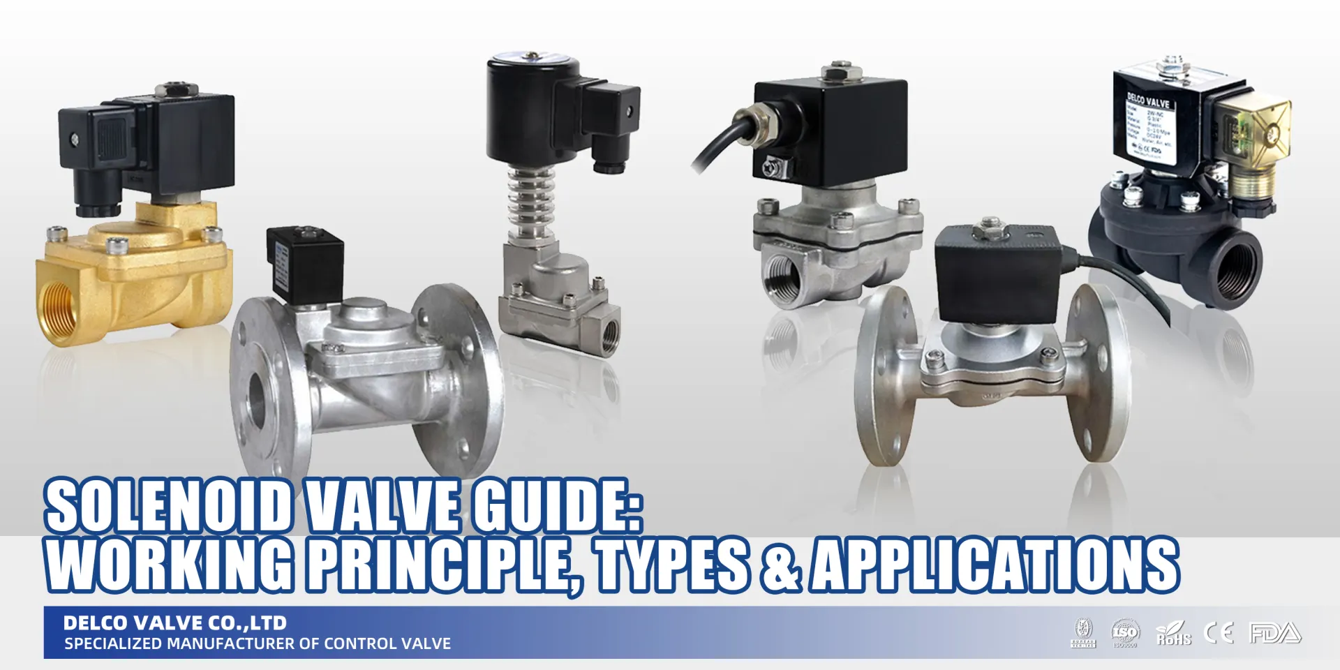
- Solenoid Pilot Valve: This acts as the electric switch. We typically use a 3-way or 5-way [Solenoid Valve] (NAMUR mount) to direct the airflow into the actuator cylinders based on signals from your control system.
- Limit Switch Box: You need to know where your valve is. These switches send a signal back to the control room confirming if the valve is fully open or fully closed.
- Positioners: For applications requiring flow modulation rather than just on/off service, a positioner adjusts the valve stroke based on a 4-20mA signal.
- Air Filter Regulators: Dirty air kills actuators. We always install these to clean the air and keep the pressure constant.
Would you like me to detail the specific maintenance checklist for the piston seals in double-acting actuators next?
Pneumatic Gate Valve Working Principle
Understanding the pneumatic gate valve working principle is easier than it looks. At its core, we are converting the energy of compressed air into mechanical motion to manage flow. Unlike rotary valves (like butterflies or balls), a gate valve requires a vertical up-and-down movement. Therefore, we use a linear actuator to drive the piston rod and valve stem, ensuring a precise linear stroke that lifts or seats the gate wedge.
Here is the step-by-step breakdown of how we get that massive steel gate to move using just air:
- Air Supply: Compressed air (typically 4-8 bar / 60-115 PSI) is fed into the actuator cylinder.
- Piston Movement: The air pressure pushes against an internal piston or diaphragm.
- Stem Actuation: This force moves the connected stem and gate linearly to either block or allow fluid flow.
Double Acting vs Single Acting Cylinder Configurations
When selecting an actuator, you are usually choosing between two main operation styles. This choice defines how the valve reacts if you lose air pressure.
- Double Acting Pneumatic Actuator: This setup uses air pressure for both directions. We supply air to one port to open the valve and air to a second port to close it. It provides consistent force in both directions but has no intrinsic safety position if the air supply fails.
- Single Acting (Spring Return): This is often called a fail safe pneumatic gate valve. We use air pressure to compress a heavy-duty spring and open the valve. If the air supply is cut off or the power dies, that spring return mechanism immediately forces the piston back, snapping the gate into a safe position (usually Closed) automatically.
Precision Control with Solenoid Pilot Valves
To automate this linear pneumatic actuator working process, we don’t just blast air into the cylinder manually. We integrate a solenoid pilot valve. This device acts as the “switch,” receiving electrical signals from your control system to direct the airflow. By regulating the air entry and exhaust, we achieve a smooth, controlled stroke, preventing the air operated gate valve from slamming shut and causing water hammer.
Would you like me to help you create a comparison table for the next section to highlight when to choose pneumatic over electric actuators?
Pneumatic Actuator Advantages and Key Benefits
When we look at automating industrial lines, the pneumatic actuator gate valve often wins out over electric or hydraulic options. In my experience running efficient systems, it usually comes down to a mix of raw speed, safety, and the bottom line. Here is why I recommend these for heavy-duty applications.
Fast Response and High-Speed Operation
Time is money, but in emergencies, time is safety. Pneumatic actuators utilize compressed air to drive the piston immediately. Unlike electric actuators that need time to gear up, air power provides fast response times. This allows for quick shut-off capabilities, which are vital for emergency isolation in volatile pipelines.
Intrinsic Safety and Durability
In the US oil and gas sector, safety is non-negotiable. Air operated gate valves are inherently safer in hazardous environments. Since they run on air rather than electricity, there is no risk of sparking, making them an explosion-proof design ideal for combustible zones. They are also incredibly durable; the simple mechanical design withstands harsh conditions with minimal wear.
Cost-Effectiveness and Clean Operation
From a business standpoint, pneumatic systems offer excellent ROI. They are generally more cost-effective to install and maintain than complex hydraulic or electric systems. Plus, there is no risk of hydraulic oil leaks, ensuring a cleaner operation that meets strict environmental standards.
Quick Benefit Breakdown:
- Fail-Safe Reliability: With a single-acting setup, you get a fail safe pneumatic valve that automatically returns to a safe position (open or closed) if the air supply cuts out.
- Easy Integration: These valves integrate seamlessly with automation systems (PLC/DCS) using standard solenoid valves and limit switches.
- Low Maintenance: Fewer moving parts mean less downtime and lower long-term service costs.
Would you like me to create a comparison table showing exactly when to choose pneumatic over electric actuators for your specific facility?
Pneumatic vs. Electric vs. Hydraulic Actuators for Gate Valves
Choosing the right muscle for your gate valve automation isn’t just about price; it’s about matching the power source to your specific infrastructure. While I deal heavily with pneumatic actuator gate valves, it’s crucial to understand how they stack up against the competition to make an informed decision for your facility.
Quick Comparison: Speed, Cost, and Performance
Here is a breakdown of how pneumatic vs electric gate valves (and hydraulic options) perform in typical US industrial settings.
| Feature | Pneumatic Actuator | Electric Actuator | Hydraulic Actuator |
|---|---|---|---|
| Power Source | Compressed air (60-100 PSI) | Electricity (AC/DC) | Hydraulic Fluid (Oil) |
| Operating Speed | Fast (Adjustable) | Slow (Gear reduction) | Moderate to Fast |
| Initial Cost | Low | Moderate to High | High |
| Torque/Thrust | Low to Medium | Medium | Extremely High |
| Precision Control | Moderate (Good for On/Off) | High (Best for modulation) | High |
| Safety (Explosion) | Intrinsically Safe (Spark-free) | Requires NEMA 7/Ex rating | Risk of fluid ignition |
| Fail-Safe Mode | Easy (Spring return) | Complex (Battery backup) | Complex (Accumulators) |
| Maintenance | Low (Clean air required) | Moderate (Gears/motors) | High (Fluid leaks/filters) |
When Pneumatic Excels
For most industrial gate valve applications, pneumatic is the industry workhorse. If your facility already has a reliable compressed air supply, this is usually the most cost-effective route.
I recommend sticking with pneumatic when:
- Safety is critical: In volatile environments like oil refineries or chemical plants, air doesn’t spark. An air operated gate valve is inherently explosion-proof without expensive housing.
- Speed matters: If you need a quick shut-off during an emergency, pneumatic cylinders react almost instantly.
- Simple Logic: Achieving a fail safe pneumatic valve setup is as simple as using a single acting spring return actuator. If air is lost, the spring forces the valve closed (or open) automatically.
Scenarios Favoring Electric or Hydraulic
While pneumatic actuator advantages are clear for isolation valves, there are times we have to look elsewhere:
- Electric: Go this route when you need ultra-precise flow control (modulation) rather than just open/close functions. They are also necessary in remote locations where running air lines isn’t feasible, but electricity is available.
- Hydraulic: This is for the heavyweights. When you are dealing with massive pipeline valves that require immense torque to crack open against high differential pressure, hydraulic fluid offers the non-compressible force needed to get the job done.
The Bottom Line
If you need reliable, fast, and safe open/close automation for standard piping, the pneumatic gate valve working principle offers the best ROI. It keeps maintenance low and safety high. However, for specialized throttling or extreme force, we can look at electric or hydraulic alternatives.
Would you like me to create a checklist for sizing your compressor to match a specific pneumatic actuator?
Industrial Gate Valve Applications and Real-World Use
When you walk through a major industrial facility in the US, you are going to see pneumatic actuator gate valves doing the heavy lifting. I’ve found that whenever an application requires high torque, fast switching speeds, or intrinsic safety, these valves are the first choice over electric alternatives.
Here is where we see the pneumatic gate valve working principle delivering the most value:
Key Industries Utilizing Pneumatic Actuation
- Oil & Gas: This is arguably the biggest market. We use fail safe pneumatic gate valves for pipeline isolation and emergency shut-down (ESD) systems. In remote fields or refineries, a single acting spring return actuator is critical; if the air supply or power cuts out, the spring forces the valve closed to prevent a blowout.
- Water and Wastewater Treatment: Dealing with sludge and slurry requires a specialized approach. This is the prime spot for a pneumatic knife gate valve application. The sharp edge of the gate cuts through suspended solids that would jam a standard wedge gate, while the pneumatic cylinder provides the force needed to seal it tight.
- Chemical and Petrochemical: Safety is the priority here. Since compressed air doesn’t generate sparks, an air operated gate valve is inherently explosion-proof. They handle corrosive, viscous, and volatile fluids where electric actuators might pose a fire risk.
- Power Generation and Mining: These environments are harsh. We use heavy-duty actuators to manage high-pressure steam in power plants or abrasive slurries in mining operations. The sheer thrust of a large piston is necessary to overcome the line pressure.
- Pulp & Paper: The media here—heavy pulp stock—is thick and difficult to manage. Pneumatic automation allows for rapid, frequent cycling to control batch processes efficiently.
Real-World Performance
In practice, the choice often comes down to the specific setup. For example, in a factory with an existing air loop, utilizing a double acting pneumatic actuator is significantly cheaper and faster than wiring up high-voltage electric actuators. Whether it is controlling flow in a food processing plant or managing “dirty” media in a paper mill, integrating these valves with a solenoid pilot valve allows for precise, automated control from a central room.
If you have compressed air available and need reliable, high-force automation, this technology is the industry standard for a reason.
Would you like me to create a checklist for selecting the right size actuator for your specific pipeline pressure?
Selection and Installation Guide for Pneumatic Gate Valves
Getting the right equipment for your pipeline isn’t just about picking a size and hoping for the best. Through my experience supplying industrial automation solutions across the States, I’ve seen that proper selection and installation are exactly what separates a smooth operation from a maintenance nightmare. Here is how we ensure you get the right pneumatic actuator gate valve for the job.
Key Factors for Valve Selection
Before we even look at a catalog, we need to nail down the specifics of your process. Gate valves require linear force, so we aren’t just looking at torque—we are looking at thrust.
- Thrust Requirements: The actuator must generate enough force to overcome the friction of the wedge against the seats, especially under maximum differential pressure.
- Media Characteristics: Are you handling clean water, or is this a knife gate valve pneumatic application for slurry? Viscous or abrasive media requires a higher safety factor (usually an extra 25-30% thrust).
- Operating Pressure: We need to know your available plant air pressure (typically 80-100 PSI). A drop in air pressure means a drop in output force.
- Fail Position: Do you need a fail safe pneumatic valve? If the power or air cuts out, does the valve need to fail open (FO) or fail closed (FC)? This dictates whether we use a single acting spring return actuator or a double-acting one.
Sizing the Actuator to the Valve
Sizing is where the rubber meets the road. A linear pneumatic cylinder gate valve relies on a precise match between the cylinder’s stroke and the valve’s travel.
- Linear Stroke Matching: The stroke length of the piston rod must align perfectly with the gate travel. If the stroke is too short, the valve won’t fully open; too long, and you risk damaging the valve seat or the stem.
- Cylinder Bore Size: We calculate the bore size based on the required thrust and your available compressed air supply.
- Mounting Interface: We usually look for ISO 5210 or MSS SP-101 standard mounting flanges to ensure a solid connection between the bonnet and the actuator.
Best Practices for Installation
Even the best hardware will fail if installed poorly. When we send these out, I always advise my clients to follow a strict setup protocol to protect the piston rod and seals.
- Vertical Alignment: Whenever possible, install the valve with the stem in a vertical position. This reduces side-loading wear on the actuator seals.
- Air Supply Setup: Dirty air is the enemy. Always install a filter regulator and lubricator (FRL) unit upstream. This ensures the air entering the cylinder is clean, dry, and oiled, preventing premature wear on the air operated gate valve.
- Support: For larger valves (10 inches and up), the weight of the pneumatic cylinder can be significant. You might need external support to prevent stress on the pipeline.
Integration with Control Systems
To get that true “set it and forget it” automation, you need the right accessories hooked up to your PLC or DCS.
- Solenoid Pilot Valve: This is the control interface. We typically mount a NAMUR standard solenoid pilot valve directly to the actuator to control air flow.
- Feedback Monitoring: Install a limit switch box or proximity sensors. This gives your control room real-time confirmation of whether the valve is fully open or closed.
- Speed Control: If you need to prevent water hammer, install exhaust speed control mufflers to slow down the opening or closing speed of the linear stroke.
Maintenance and Pneumatic Actuator Troubleshooting
I always tell my customers: reliable operation starts with a solid maintenance schedule. You don’t want a pneumatic actuator gate valve failing during a critical shut-off. Keeping these valves running smoothly is usually straightforward if you stay ahead of the wear and tear.
Routine Checks
To avoid unexpected downtime, keep an eye on these basics during your walkthroughs:
- Air Leaks: Listen for hissing sounds. A simple soapy water test on fittings and the limit switch box connections helps spot leaks early.
- Seals and Gaskets: Inspect the piston rod seals for wear. If air escapes here, you lose torque and efficiency.
- Air Supply Quality: Ensure your compressed air is clean and dry. Moisture and dust are the biggest enemies of pneumatic components.
Troubleshooting Common Issues
If your valve acts up, here is a quick cheat sheet for air operated gate valve troubleshooting:
| Symptom | Probable Cause | Quick Fix |
|---|---|---|
| Slow Response | Low air pressure or clogged exhaust | Check supply pressure (usually 4-8 bar); clean silencers. |
| Valve Won’t Stroke | Faulty solenoid pilot valve | Test the coil and power supply; replace if dead. |
| Sticking Gate | Debris or dry stem | Flush the valve body to clear obstruction; grease the stem. |
| Drifting Position | Internal cylinder leak | Replace internal piston seals or O-rings. |
Tips for Extending Service Life
Want your linear pneumatic cylinder gate valve to last? Install a good filter-regulator-lubricator (FRL) unit right before the actuator. Clean, lubricated air prevents the internal cylinder from getting gummed up. Also, if a valve sits idle for long periods, cycle it occasionally to keep the seals flexible and ensure the fail safe pneumatic valve function is ready when you need it.
Share on Social: