Safety Valves: A Complete Guide to Principles, Types, and Applications
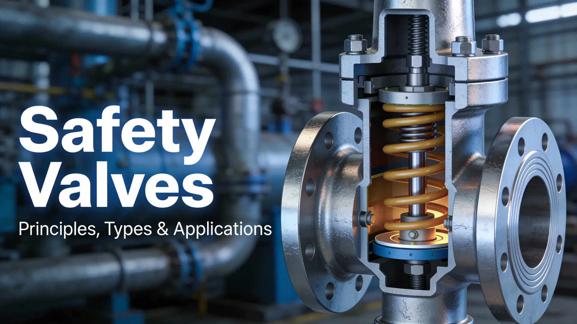
Safety Valves: A Complete Guide to Principles, Types, and Applications
Dec 28, 2025

What Is a Valve: A Complete Guide to Types, Parts, Functions, and Selection
Dec 26, 2025
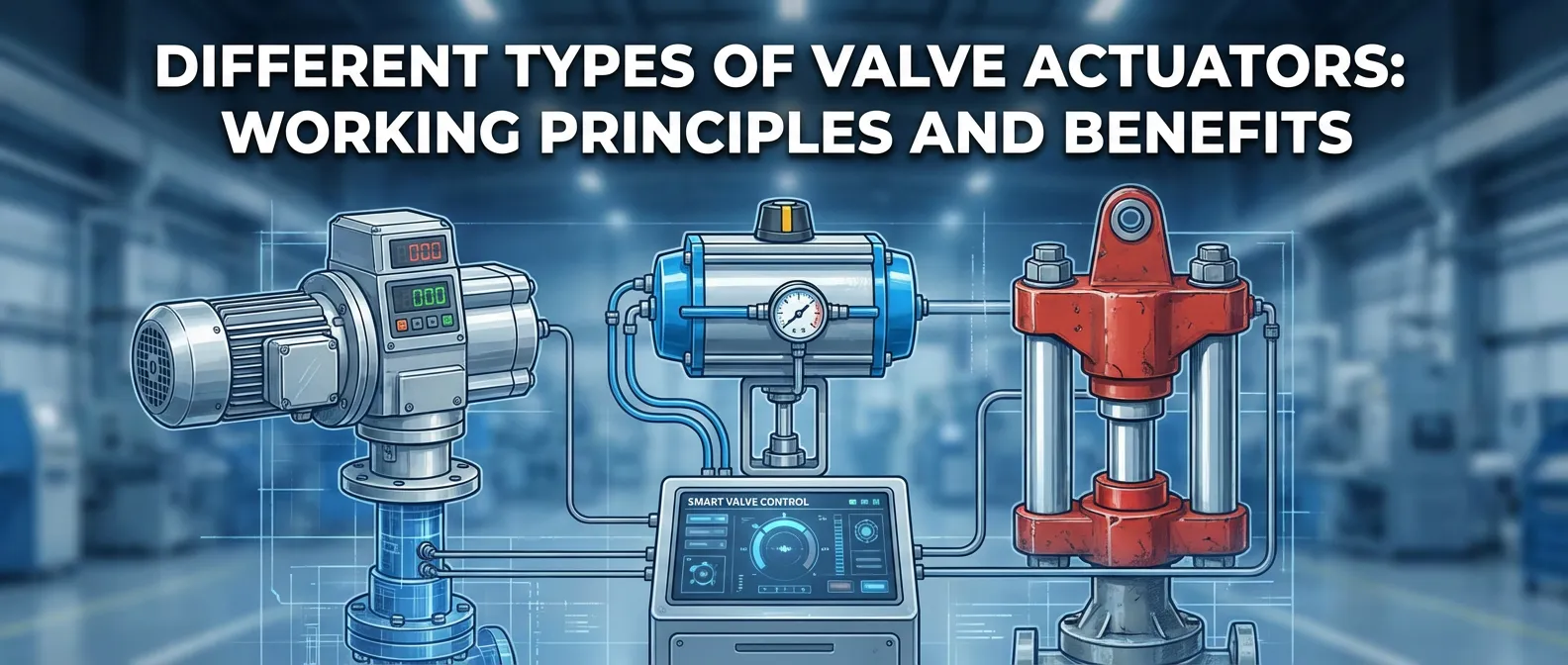
Different Types of Valve Actuators Working Principles and Benefits
Nov 29, 2025
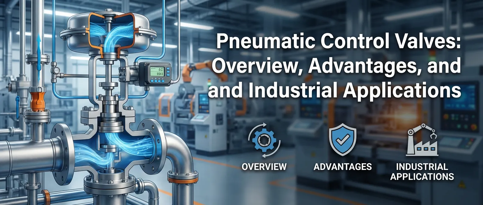
Pneumatic Control Valves Overview Advantages and Industrial Applications
Nov 29, 2025
You likely understand that safety valves are the critical last line of defense for any pressure system. But do you truly grasp the physics behind the force balance equation, or when to specify a balanced bellows valve? Improper selection risks personnel safety and catastrophic equipment failure.
In this technical guide, we provide a comprehensive breakdown of:
- Pressure Safety Valve (PSV) principles and force balance physics.
- Overpressure Protection standards (ASME Section I & VIII).
- Key differences between Safety Valves (gas) and Relief Valves (liquid).
- Selection criteria for Pilot-Operated vs. Spring-Loaded designs.
From decoding ASME Boiler Code compliance to mastering set pressure and blowdown, you’re going to get the actionable insights needed to ensure total process integrity. Let’s get into the details.
Fundamental Principles of Operation
When we talk about overpressure protection, we are dealing with the last line of defense for your personnel and plant assets. Understanding how a safety valve actually functions is critical for proper selection and safety compliance. It isn’t magic; it is pure physics and precision engineering.
The Force Balance Equation
At the heart of a spring-loaded safety valve, operation relies on a continuous battle between two opposing forces. We have the process pressure pushing up against the valve disc, and the spring force pushing down to keep it closed.
The valve remains closed as long as the downward force of the spring exceeds the upward force of the system pressure. The moment equilibrium is reached, the valve begins to open. We express this force balance relationship with the following simple equation:
F(spring) = P(inlet) × A(seat)
Where:
- F(spring): The mechanical force exerted by the spring (pushing down).
- P(inlet): The fluid pressure acting on the disc (pushing up).
- A(seat): The area of the seat exposed to the fluid.
Key Performance Parameters
To specify the right pressure relief valve, we need to agree on the terminology. These parameters define exactly when the valve opens, how much it flows, and when it closes.
- Set Pressure: The specific inlet static pressure at which the valve begins to open (lift).
- Overpressure: The pressure increase above the set pressure, usually expressed as a percentage, necessary for the valve to reach full lift and capacity.
- Accumulation: The pressure increase allowed in the pressure vessel during discharge (governed by ASME Section VIII or Section I).
- Blowdown Percentage: The difference between the set pressure and the valve reseating pressure. We need a specific drop in pressure to allow the spring to snap the valve shut again.
Pop Action vs. Proportional Opening
The physical state of the media dictates the valve’s behavior. We design safety valves for compressible fluids (steam/gas) and relief valves for incompressible fluids (liquids).
- Pop Action Valve (Gas/Steam): As the disc lifts, the escaping gas expands rapidly against a larger area (the huddling chamber). This sudden increase in upward force causes the valve to “pop” fully open almost instantly.
- Proportional Opening (Liquids): Liquids do not expand. Therefore, the valve opens gradually (proportionally) as the pressure increases.
Understanding Back Pressure Effects
Back pressure refers to the pressure existing at the outlet of the valve. Ignoring this is a common cause of valve instability and chatter. We categorize this into two types:
- Superimposed Back Pressure: Pressure already present in the discharge header before the valve opens. It effectively adds to the spring force, increasing the set pressure.
- Built-up Back Pressure: Pressure that develops in the discharge piping after the valve opens due to fluid flow.
If your system has variable back pressure, a standard conventional design might fail. In those cases, we look toward balanced bellows valves to neutralize these forces.
Simmer and Lift Characteristics
Before the valve fully pops, you will often encounter simmer. This is the audible “hissing” sound caused by the extremely slight separation of the disc and seat just before the set pressure is reached. It serves as a warning.
Lift is the actual travel of the disc away from the seat. In a safety relief valve, achieving full lift at the specified overpressure is vital to ensure the valve discharges its rated capacity and prevents catastrophic vessel failure.
Would you like me to detail the specific design differences between Direct Spring-Loaded and Pilot-Operated valves next?
Unlike standard flow control devices such as gate or globe valves (see our complete guide on What Is a Valve: Types, Parts, and Functions), safety valves are purely designed for overpressure protection.
Main Types of Safety Valves
Selecting the correct Pressure Safety Valve (PSV) is critical for system reliability. It isn’t just about the pipe size; it is about selecting the internal mechanism that handles your specific process conditions. We generally categorize these into three primary designs found in most US industrial facilities, alongside specific lift configurations.
Direct Spring-Loaded Safety Valves
This is the conventional standard for most general applications. In this design, a calibrated spring holds the disc against the seat, opposing the system pressure. They are durable, cost-effective, and fail-safe. However, standard spring-loaded safety valves have limitations; they are susceptible to the effects of backpressure. If the pressure in the discharge piping fluctuates, it directly changes the opening pressure of the valve, which can compromise safety in complex piping networks.
Balanced Bellows Safety Valves
When we deal with variable or high backpressure (typically anything over 10% of the set pressure), the conventional design fails to perform accurately. That is where the balanced bellows valve comes in. By incorporating a metal bellows element, we shield the spring and guide surfaces from the process fluid. This design effectively neutralizes back pressure effects, ensuring the valve opens at the correct set pressure regardless of resistance in the outlet piping.
Pilot-Operated Safety Valves
For high-pressure applications or situations requiring operation very close to the set point, we utilize the pilot-operated safety valve. Unlike the spring-loaded types where pressure pushes the valve open, a pilot valve uses the system pressure to hold the main valve closed. This results in superior tight shutoff efficiency—the higher the pressure, the tighter the seal, until the pilot triggers the release. These are excellent for minimizing product loss and handling large capacities.
Specialized Lift Designs
Beyond the actuation mechanism, we must consider the lift characteristics:
- Low-lift designs: Generally used for incompressible fluids (liquids) where the valve opens proportionally to relieve pressure.
- Full-lift designs: Essential for compressible media like steam and gas. These valves pop open rapidly to the full discharge area to handle rapid volume expansion.
Would you like me to detail the specific sizing formulas required for these different valve types in the next section?
Key Differences: Safety Valves vs. Relief Valves vs. Safety Relief Valves
In the industrial world, terms like “safety valve” and “relief valve” are often used interchangeably, but there are distinct technical differences that determine which device protects your system. Understanding the difference between safety valve and relief valve terminology is critical for compliance with ASME Code and API Standards, ensuring you have the right overpressure protection for your specific media.
Terminology Distinctions and Operation
The core difference lies in the opening characteristic and the type of fluid handled.
- Safety Valve: Characterized by rapid, full opening or “pop action.” It is designed primarily for compressible fluids (steam, gas, air). When the set pressure is reached, the valve snaps open to release pressure immediately to prevent a catastrophe. This is the standard for boiler safety and gas lines.
- Relief Valve: characterized by a gradual or proportional opening. As pressure increases above the set point, the valve opens further. These are strictly for incompressible media (liquids like water or oil) where rapid popping could cause damaging water hammer.
- Safety Relief Valve: A versatile hybrid design. It can function as a safety valve (pop action) for gas or as a relief valve (proportional) for liquid, depending on the application.
If you are looking to source specific protection devices, exploring our valve product categories will help you identify the exact configuration needed for your facility.
Comparison: Safety Valve vs. Relief Valve
| Feature | Safety Valve | Relief Valve | Safety Relief Valve |
|---|---|---|---|
| Action | Rapid “Pop” Opening | Gradual (Proportional) | Dual (Pop or Gradual) |
| Primary Media | Compressible (Steam, Gas) | Incompressible (Liquid) | Gas, Vapor, or Liquid |
| Standard | ASME Section I & VIII | ASME Section VIII | ASME Section VIII |
| Outlet Pressure | Generally atmospheric | Discharges to lower pressure system | Atmospheric or closed system |
If you are looking to source specific protection devices, exploring our Safety Valve Product Categories will help you identify the exact configuration needed for your facility.
Application Guidelines: Compressible vs. Incompressible
Selecting the wrong type isn’t just a code violation; it’s a safety hazard.
- Use Safety Valves for steam boilers, air receivers, and gas processing. The expansive nature of gas requires immediate volume release.
- Use Relief Valves for hydraulic systems, oil pipelines, and water pumps. The proportional opening stabilizes pressure without shocking the piping system.
By strictly adhering to these definitions, we ensure that our pressure safety valve (PSV) selection meets the rigorous demands of industrial safety.
Would you like me to detail the specific sizing formulas used for compressible versus incompressible fluids in the next section?
Industrial Applications of Safety Valves: Principles, Types, and Applications in Action
When we look at safety-valves-principles-types-and-applications across the board, it’s clear these devices are the backbone of plant safety. In my experience, selecting the right valve depends entirely on the specific demands of the industry, whether we are dealing with volatile gas or high-pressure steam.
Here is where we typically see these valves doing the heavy lifting:
Oil & Gas and Petrochemical Protection
In the energy sector, pressure vessel protection is our top priority. We use robust Pressure Safety Valves (PSV) to safeguard pipelines, separators, and storage vessels from catastrophic failure.
- Upstream: Handling raw crude and natural gas with high particulate matter.
- Downstream: Protecting refining columns where temperature and pressure fluctuate wildy.
- Role: These valves prevent system rupture during process upsets or fire exposure.
Power Generation and Boiler Systems
You cannot run a power plant without reliable overpressure protection. In this industry, the boiler safety valve is the final line of defense.
- Boiler Drums: We install these to handle the immense expansion of steam.
- Superheaters: Specialized valves ensure the superheater doesn’t overheat if the main flow stops.
- Compliance: These applications strictly follow ASME Section I codes to manage steam accumulation effectively.
Chemical and Pharmaceutical Processing
This sector presents unique challenges regarding material compatibility and hygiene. We often specify a balanced bellows valve or a specialized safety relief valve here to handle:
- Corrosive Media: Using exotic alloys to prevent valve degradation from aggressive chemicals.
- Hygienic Needs: In pharma, we use flush-mounted, sanitary valves to prevent bacteria buildup.
- Toxic Containment: Ensuring zero leakage to the atmosphere is critical for personnel safety.
Marine and General Industry
Beyond the major processing plants, we apply pressure relief valve technology in marine and general manufacturing environments.
- Marine: Protecting ship boilers and cargo systems from thermal expansion.
- High-Pressure Water: preventing damage in hydraulic cleaning systems.
- General Storage: Simple protection for air receivers and utility lines.
Would you like me to detail the specific ASME and API standards required for these industries next?
Standards and Regulatory Compliance

When we discuss safety-valves-principles-types-and-applications, we aren’t just talking about mechanical function; we are talking about legal and safety obligations. In the United States, compliance isn’t optional—it is the difference between a secure facility and a catastrophic failure. Navigating the regulatory landscape can be tricky, but it usually boils down to knowing which specific code applies to your equipment.
ASME Section I vs. ASME Section VIII
The ASME Code is the governing law for pressure equipment in the US. The most critical distinction I make when selecting valves is between fired and unfired vessels:
- ASME Section I: This is strictly for fired pressure vessels. If you are dealing with a boiler safety valve on a power boiler operating above 15 psig, it must meet these rigorous standards.
- ASME Section VIII: This covers unfired pressure vessel protection. This is the standard used for the vast majority of process tanks, accumulators, and piping systems in petrochemical and general industries.
API Standards Recommendations
While ASME provides the rules, the API Standards provide the practical roadmap for the oil and gas industry. These are the guidelines I follow (you can view our compliant specs in the Download Center):
- API 520: The definitive guide for sizing and selection. It gives us the formulas to calculate the required orifice area.
- API 526 standards: This specifies the standard dimensions and pressure ratings for flanged steel pressure relief valves. It ensures that a valve from one manufacturer will physically fit in the spot of another.
- API 527: This sets the acceptance criteria for seat tightness. If you are worried about leakage, this is the standard that defines how much (if any) is allowable.
Certification and Third-Party Testing
International projects might refer to ISO 4126, but in the domestic US market, the National Board certification is king. Never install a safety device that lacks the proper certification marks (like the “V” stamp for boilers or “UV” stamp for pressure vessels). These stamps prove the valve has undergone rigorous third-party testing and will perform exactly as the nameplate says it will.
Would you like me to create a checklist for verifying valve nameplate data against ASME and API requirements?
Safety Valve Selection Criteria

Selecting the right valve isn’t just about matching pipe sizes; it’s about ensuring reliable overpressure protection when your system needs it most. When I spec out a job, I start by analyzing the specific operating conditions to guarantee the valve doesn’t just fit, but actually works.
Critical Factors: Media, Temperature, and Pressure
You have to know exactly what is flowing through the line. The state of the medium dictates the valve type:
- Media Type: Use a standard safety valve for compressible fluids (gas/steam) to get that rapid “pop” action. For incompressible liquids, a relief valve or safety relief valve is necessary to handle proportional opening.
- Operating Conditions: High temperatures can weaken spring materials, altering the set pressure. Always match the temperature rating of the valve body and trim to your maximum operating temp.
- Back Pressure: This is the silent killer of valve performance. You must determine if the back pressure is constant or variable.
Handling Back Pressure Effects
If your system vents into a manifold with fluctuating pressure, a conventional spring-loaded safety valve won’t cut it. The variable back pressure acts on the top of the disc, changing the opening pressure.
- Variable Back Pressure: I recommend using a balanced bellows valve or a pilot-operated safety valve. These designs isolate the bonnet or pilot from downstream pressure changes, ensuring the valve pops exactly at the set limit.
Sizing Basics and Materials
Sizing isn’t a guessing game. We use flow equations compliant with ASME Section VIII and API 526 standards to determine the required effective orifice area.
- Don’t Oversize: A valve that is too big for the required capacity will open and slam shut repeatedly (chatter), destroying the seat and causing leakage.
- Material Compatibility: For the body and trim, compatibility is non-negotiable. Standard Carbon Steel works for general utility, but if you are handling corrosive chemicals or extreme temperatures, upgrade to Stainless Steel or Monel (essential for Marine Valve applications) to prevent the disc from seizing.
Common Pitfalls to Avoid
- Ignoring Inlet Pressure Drop: Ensure the pressure drop in the piping leading to the valve is less than 3% of the set pressure, or the valve will chatter.
- Confusing Valve Types: Never use a Section VIII valve on a boiler application requiring ASME Section I compliance.
- Neglecting Accumulation: Make sure the valve can discharge the full capacity without exceeding the allowable accumulation limits of the vessel.
Installation, Testing, and Maintenance Best Practices
When I look at the lifecycle of safety-valves-principles-types-and-applications, I always emphasize that selecting the right valve is only half the battle. The way you install and maintain these devices dictates whether they will save your equipment or become a liability. We need to focus on strict adherence to standards like API 576 to ensure longevity and safety.
Proper Inlet/Outlet Piping to Prevent Chatter
The most common killer of a pressure relief valve isn’t the pressure itself; it’s poor piping design. If your inlet piping causes a pressure drop greater than 3% of the set pressure, you are going to experience chatter. This rapid opening and closing acts like a jackhammer on the valve, destroying the seat and disc in seconds.
To avoid this, I recommend:
- Keep inlet lines short: Mount the valve directly on the nozzle if possible.
- Check the outlet: Ensure the discharge piping is supported independently so it doesn’t induce stress on the valve body.
- Manage back pressure: Undersized discharge lines create excessive built-up back pressure, reducing the valve’s capacity.
In-Service Testing Methods: Online vs. Offline
You don’t always have to shut down the plant to verify your safety relief valve is working. While offline bench testing is the gold standard for a full overhaul and seat tightness check, it requires downtime.
For critical continuous processes, online testing (often using hydraulic assist devices) allows us to verify the set pressure without lifting the valve fully. This satisfies regulatory requirements while keeping production running. However, if the valve is leaking or damaged, offline maintenance is the only real fix.
Troubleshooting Common Issues
In my experience, three issues account for 90% of service calls: leakage, simmer, and frequent popping. Here is how I break them down:
- Leakage: Usually caused by debris stuck between the seat and disc or misalignment from piping stress. If you don’t catch this early, the high-velocity fluid will cut grooves in the sealing surface (wire drawing).
- Simmer (Pre-open): If the valve is audible or “simmering” before the set pressure, the operating pressure is likely too close to the set point. You generally need a differential of at least 10%.
- Frequent Popping: This suggests the pressure vessel protection limit is being hit due to upstream process control failures (consider upgrading your Globe Control Valves for better regulation).
Recommended Inspection Intervals per API 576
We don’t guess when it comes to maintenance schedules. I strictly follow API 576 standards for inspection intervals. For a new installation in clean service, a standard interval might be 1 to 3 years. However, if you are handling corrosive materials or fouling services (like in a coker unit), that interval drops significantly. Regular scheduled inspections prevent the valve from sticking (fouling) and ensure the blowdown and lift characteristics remain within spec.
Share on Social:
- PREV: What Is a Valve: A Complete Guide to Types, Parts, Functions, and Selection
- NEXT: Not NEXT
Contact Us
In This Article
Safety Valves: A Complete Guide to Principles, Types, and Applications
Dec 28, 2025
What Is a Valve: A Complete Guide to Types, Parts, Functions, and Selection
Dec 26, 2025
Different Types of Valve Actuators Working Principles and Benefits
Nov 29, 2025
Pneumatic Control Valves Overview Advantages and Industrial Applications
Nov 29, 2025