 Home /
 Pneumatic Ball Valve Selection Guide Expert Tips for Optimal Sizing
Comprehensive Pneumatic Ball Valve Selection Guide covering materials sizing actuators and industrial applications for optimal valve performance and safety.
Introduction to Pneumatic Ball Valves
Automating industrial pipelines requires precision, reliability, and speed. Pneumatic ball valves represent the gold standard for efficient on/off service and flow control in demanding environments. By utilizing compressed air to generate rotary motion, these assemblies offer a robust solution for modernizing industrial processes, replacing manual labor with consistent automatic actuation.
A Quick Selection Checklist (5 factors engineers must confirm)
Before specifying a valve, engineers must validate these five critical parameters to ensure durability and performance while avoiding costly downtime:
- Fluid Type & Characteristics: Is the media corrosive, abrasive, or viscous? This dictates the material selection for the body and seals.
- Operating Conditions: Verify that the working pressure and operating temperature fall strictly within the valve’s rating.
- Torque Calculations: Determine the break valve torque and add a safety margin (typically 25-30%) to size the actuator correctly.
- Actuation Mode: Choose between Double Acting (DA) for standard control or Spring Return (SR) for failsafe requirements.
- Mounting Standards: Confirm ISO 5211 mounting dimensions to ensure the actuator couples seamlessly with the valve stem.
What is a Pneumatic Ball Valve? (Speed & Automation)
A pneumatic ball valve is a unified assembly consisting of a process valve (the ball valve body) mated to a pneumatic actuator. Unlike manual valves that require human intervention, these devices utilize air pressure acting on internal pistons to convert linear force into quarter-turn rotary motion. This mechanism allows for rapid cycling, making them ideal for high-speed applications where immediate flow diversion or isolation is critical. The design typically features quarter-turn valves, which move from fully open to fully closed with a 90-degree rotation.
Why Choose Pneumatic? (Safety, Speed, and Cost-Efficiency)
Pneumatic systems often outperform electric counterparts in heavy-duty industries due to their simplicity and power density. They provide high torque output relative to their size and offer distinct advantages in hazardous environments.
| Feature | Benefit |
|---|---|
| Intrinsic Safety | Operates without electricity at the valve, eliminating spark risks in explosive atmospheres. |
| Response Speed | Achieves rapid opening and closing times, essential for emergency shutdowns. |
| Cost-Efficiency | Generally lower cost than electric actuators for high-torque and large valve sizes. |
| Durability | Simple mechanical design withstands harsh environmental conditions and high cycle rates. |
Common Industrial Applications: From Water Treatment to Chemical Dosing
Pneumatic ball valves are the workhorses of fluid automation, deployed wherever reliable isolation is required.
- Water & Wastewater: Controlling sludge lines and chemical dosing skids.
- Chemical Processing: Managing aggressive acids and solvents using lined 2-way ball valves.
- Oil & Gas: Critical Emergency Shutdown (ESD) systems utilizing spring return actuators to close valves upon air failure.
- Food & Beverage: Sanitary lines requiring frequent washdowns and clean-in-place (CIP) compatibility.
Defining Process Conditions: The First Step in Selection
Before we even look at the actuator or the mounting standards, we have to start with the basics: what is actually going through the pipe? I see too many engineers skip straight to the mechanics without fully defining the process conditions. This is the foundation of any reliable Pneumatic Ball Valve Selection Guide. If you get the process data wrong, the best valve in the world won’t last a week.
We need to look at the specific environment inside the pipeline. This involves three critical factors: the media itself, the pressure/temperature relationship, and the flow requirements.
Media Compatibility: Corrosive, Abrasive, or Viscous?
The fluid type dictates the material selection for the entire valve assembly. You cannot treat clean water the same way you treat sulfuric acid or cement slurry. When I assess a project, I break the media down into three categories to determine the right body and sealing materials:
- Corrosive Media: If you are handling acids, bases, or saline solutions, standard Carbon Steel (WCB) won’t cut it. You need Stainless Steel (CF8M) or even specialized alloys like Hastelloy. For extreme corrosion, lined valves (PFA/PTFE lined) are often the smartest choice to prevent chemical attack.
- Abrasive Media: Slurries and fluids with suspended particles act like sandpaper. Soft seats like PTFE will get chewed up quickly, leading to leaks. For these industrial processes, I recommend metal-seated valves or hardened seat materials to ensure durability and performance.
- Viscous Fluids: Thick media like heavy oils, resins, or food pastes create drag. This increases the torque requirements significantly. If we don’t account for this extra resistance, the actuator selection will be undersized, and the valve will stall mid-stroke.
Pressure & Temperature Ratings: Understanding the P-T Chart
Working pressure and operating temperature are not independent variables; they work against each other. A common mistake is looking at the max pressure rating of a valve (e.g., 1000 PSI) and assuming it holds that pressure at any temperature. It doesn’t.
We use a Pressure-Temperature (P-T) Chart to determine the safe operating range. Here is the reality of environmental conditions inside the valve:
- As temperature rises, pressure capability drops. A valve rated for 1000 PSI at room temperature might only handle 200 PSI at 400°F.
- Seat limitations: Standard PTFE seats start to deform or soften around 200°C (392°F). If your process runs hotter, we need to switch to PEEK or metal seats.
- Thermal cycling: Rapid temperature changes can cause expansion and contraction, affecting the seal integrity between the body and the ball.
Always verify your specific process points against the manufacturer’s P-T chart before finalizing the spec.
Flow Coefficient (Cv/Kv): Sizing for Efficiency, Not Just Pipe Size
Just because you have a 2-inch pipe doesn’t mean you automatically need a 2-inch valve. Valve sizing should be based on the flow coefficient (Cv or Kv), which measures the valve’s capacity to pass fluid.
- Cv (Imperial): The volume of water (in US gallons per minute) that flows through the valve with a pressure drop of 1 PSI at 60°F.
- Kv (Metric): The volume of water (in cubic meters per hour) with a pressure drop of 1 bar.
If you oversize the valve, you are wasting budget on a larger process valve and actuator than necessary. If you undersize it, you create a bottleneck, increasing pressure drop and forcing your pumps to work harder. For on/off service, we generally want a full port valve to minimize resistance. However, for flow control applications, calculating the correct Cv ensures the valve operates in a stable range without cavitation or excessive noise.
Valve Body & Configuration: Matching the Pipeline
Selecting the right Pneumatic Ball Valve Selection Guide involves more than just picking an actuator; the valve body itself must physically and functionally match your pipeline. If the connection standards or internal geometry are wrong, even the best automation won’t save the process. Here is how I break down the physical configuration to ensure a perfect fit.
End Connections & Standards: ANSI, DIN, and JIS Compliance
The first thing I verify is how the valve connects to the pipe. Mismatched mounting dimensions are a frequent cause of installation delays. You cannot force a DIN flange onto an ANSI pipe without adapters, which introduces leak points.
- Threaded (NPT/BSP): Best for smaller lines (usually under 2 inches) and lower pressures. I check if the facility uses NPT (common in the US) or BSP (common globally) to avoid thread damage.
- Flanged: The standard for industrial process valve applications. You must identify the specific standard:
- ANSI/ASME: The go-to for Oil & Gas and North American markets.
- DIN/EN: Standard for European machinery and plants.
- JIS: Often required for equipment imported from or destined for Asia.
- Tri-Clamp: Mandatory for sanitary and food-grade lines to ensure easy cleaning.
2-Way vs. 3-Way (L-Port vs. T-Port): Diverting or Mixing?
While standard 2-way ball valves handle simple on/off service, complex piping often requires redirecting flow. This is where port configuration becomes critical. I use 3-way valves to eliminate the need for multiple 2-way valves and extra T-pieces.
- T-Port (Mixing/Diverting): This design allows flow between all three ports or straight through. It is ideal for mixing two streams or diverting one stream to two different destinations.
- L-Port (Diverting Only): The L-port directs flow 90 degrees, connecting the center port to one side port at a time. It cannot connect the two side ports directly.
- Selection Tip: Always sketch the flow path before buying. Using an L-port when you need to mix fluids will stall your operation.
Floating vs. Trunnion Mounted: When to Switch for High Pressure
The internal design of the ball affects the torque requirements and the lifespan of the seats.
- Floating Ball: In this design, the ball “floats” slightly. Downstream pressure pushes the ball against the seat to create a seal. This is cost-effective and works perfectly for low-to-medium pressure and smaller sizes.
- Trunnion Mounted: When working pressure is high or the valve size exceeds 6 inches, the pressure on a floating ball creates too much friction. A trunnion design anchors the ball mechanically at the top and bottom. This reduces torque, allowing for a smaller actuator and ensuring better durability and performance in harsh conditions.
Full Port vs. Reduced Port: Balancing Flow Rate and Cost
Valve sizing isn’t just about the pipe diameter; it is about the internal bore size.
- Full Port: The hole in the ball is the same size as the pipeline. This offers zero flow restriction and the highest flow coefficient, minimizing pressure drop. I insist on full port valves for viscous fluids, slurries, or lines that need to be pigged (cleaned).
- Reduced Port (Standard Port): The bore is one size smaller than the pipe size. This creates a slight pressure drop but significantly reduces the weight and cost of the valve. For standard water or compressed air lines, reduced port valves are a smart way to manage the budget without sacrificing reliability.
Selecting the Pneumatic Actuator: The “Muscle”
When compiling a Pneumatic Ball Valve Selection Guide, the actuator is arguably the most critical component to get right. This is the “muscle” of the assembly. If the actuator cannot overcome the friction of the valve seat against the ball, the valve won’t cycle, leading to system failure. We need to match the torque output of the actuator specifically to the valve’s requirements under actual process conditions, not just theoretical lab results.
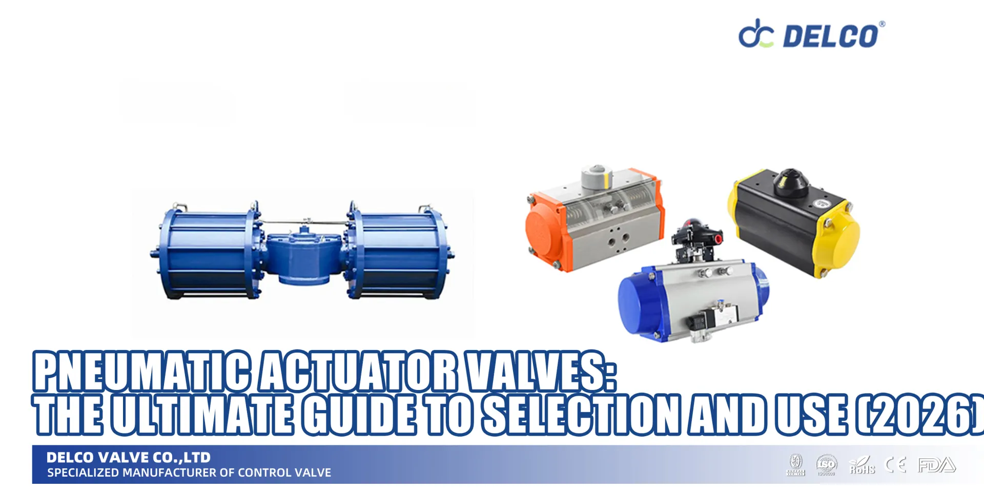
Rack & Pinion (AT) vs. Scotch Yoke (AW): Choosing the Right Mechanism
For automatic actuation in quarter-turn valves, we typically choose between two main mechanisms. Your choice depends heavily on the torque profile required by the valve size and pressure.
- Rack & Pinion (AT Series): This is the industry standard for most small to medium-sized valves. It provides a linear torque output throughout the stroke. It is compact, reliable, and cost-effective for general on/off service. We use these for the vast majority of standard applications.
- Scotch Yoke (AW Series): When dealing with large diameter valves or high-pressure applications, we switch to Scotch Yoke. This mechanism produces high torque at the beginning and end of the stroke (break-away and closing), exactly where a ball valve needs it most. It is bulkier but offers superior durability and performance for heavy-duty cycles.
The “Air Supply Trap”: How Supply Pressure Impacts Torque Output
A common mistake in actuator selection is ignoring the site’s available air pressure. Actuator manufacturers often list torque ratings based on a standard compressed air supply of 5.5 bar to 6 bar (80 PSI).
If your facility only supplies 4 bar (60 PSI), the actuator will produce significantly less torque. This is the “air supply trap.” You must verify the minimum available air pressure at the installation site. If the pressure is lower than the standard, we must oversize the actuator to compensate. Always check the cylinder specifications against your actual air supply to ensure the actuator can generate the required stroke torques.
Calculating Torque: Safety Margins for Dry vs. Lubricated Media
Valve torque is not a static number; it changes based on the fluid passing through the valve. A valve handling clean water is naturally lubricated, while a valve handling dry gas or powder faces much higher friction. We never size an actuator 1:1 with the valve’s breakout torque. We apply a safety factor based on the fluid type:
- Clean, Lubricated Liquids (Water, Oil): Add a 20% to 30% safety margin.
- Dry Media (Gas, Steam, Air): Add a 30% to 50% safety margin.
- Viscous or Slurry Media: Add a 50% to 80% safety margin.
Ignoring these margins leads to stalled actuators. We calculate the torque requirements carefully to ensure the valve cycles smoothly even after sitting idle for long periods.
Double Acting vs. Single Acting (Spring Return): Planning for Failsafe
The choice between double acting and spring return actuators is fundamentally a question of safety and budget.
- Double Acting (DA): These use compressed air to both open and close the valve. They are smaller, lighter, and less expensive. However, if the air supply fails, the valve stays in its last position.
- Single Acting (Spring Return/SR): These use air to move the valve in one direction (usually open) and mechanical springs to push it back (usually closed) when air is lost. This provides a “Fail Closed” or “Fail Open” safety function.
For critical industrial processes where a power loss could cause a spill or explosion, we always specify spring return units. While they are larger and require higher air pressure to compress the springs, the safety assurance is non-negotiable.
Material Selection: Valve Body and Seats
Getting the material selection right is the difference between a valve that lasts ten years and one that fails in ten days. I always tell clients that while the actuator provides the muscle, the valve materials provide the armor. You need to match the fluid type and operating temperature exactly to the valve construction to ensure long-term reliability.
Valve Body Materials: Stainless Steel (CF8M) vs. Carbon Steel (WCB)
The body material dictates the valve’s structural integrity and resistance to the outside environment.
- Stainless Steel (CF8M/316): This is my default for most industrial processes. It offers excellent corrosion resistance, making it perfect for chemical lines, food processing, or outdoor installations exposed to harsh environmental conditions.
- Carbon Steel (WCB): If you are running steam, oil, or gas and don’t have corrosive requirements, WCB is a solid, cost-effective choice. It handles high pressure well but requires painting or coating to stop external rust.
Seat Materials: PTFE for General, PEEK for Heat, Metal for Slurry
The seat material determines your pressure-temperature limits and the valve torque required to turn the ball.
- PTFE (Teflon): The industry standard. It provides a tight seal and has a low coefficient of friction, which keeps the actuator size down. Great for water, air, and mild chemicals up to about 180°C.
- PEEK: When the operating temperature or pressure climbs higher than PTFE can handle, PEEK is the solution. It is harder and more robust, ensuring durability and performance in demanding steam or thermal oil applications.
- Metal Seats: Soft seats cannot handle abrasive media. If you are controlling slurries, pulp, or fluids with particles, you need metal-to-metal sealing. It requires higher torque but won’t get chewed up by the flow.
Stem Seals and O-Rings: Preventing Fugitive Emissions
The stem seal is often the most overlooked part of the Pneumatic Ball Valve Selection Guide, yet it is the primary defense against leaks into the atmosphere.
- Viton (FKM): Excellent for oils, fuels, and hydrocarbons. It resists high temperatures and chemical attack.
- EPDM: The best choice for water, steam, and phosphate-ester fluids, though it is not compatible with petroleum-based oils.
Choosing the right sealing materials for the stem ensures that your process stays inside the pipe, preventing fugitive emissions and protecting the pneumatic actuator above from corrosive vapors.
Critical Accessories and Controls (NAMUR Standard)
An actuator provides the torque, but without the right controls, it is just a passive component. To integrate automatic actuation into your process control system, you need specific accessories. The industry standard here is the NAMUR standard interface. This standardized mounting face allows us to bolt accessories directly onto the actuator without needing custom fabrication or complex tubing, ensuring compatibility across different brands.
Solenoid Valves: The Pilot for Your Actuator
The solenoid valve acts as the pilot, directing the compressed air into the actuator based on an electrical signal. It is the bridge between your electrical control system and the pneumatic muscle. Selecting the right solenoid depends heavily on your actuator type:
- 3/2-Way Solenoids: Used for spring return (single acting) actuators. They supply air to open the valve and exhaust air to allow the spring to close it.
- 5/2-Way Solenoids: Used for double acting actuators. They actively direct air to both the open and close ports of the cylinder.
Always verify the voltage (24VDC, 120VAC, etc.) and the coil insulation class to match your site’s safety requirements.
Limit Switch Boxes: Remote Position Feedback
In large industrial facilities, you cannot physically inspect every valve to verify its status. A limit switch box mounts on top of the actuator and provides remote feedback to your control room (PLC or DCS).
- Visual Indication: Most boxes feature a high-visibility dome (Beacon) that clearly shows if the valve is Open or Closed from a distance.
- Electrical Feedback: Inside the box, mechanical switches or proximity sensors send a signal confirming the valve has reached its full travel.
For hazardous areas, we recommend explosion-proof switch boxes to ensure safety while maintaining precise monitoring of your on/off service.
Electro-Pneumatic Positioners: Turning a Ball Valve into a Control Valve
While ball valves are traditionally used for shut-off, adding an electro-pneumatic positioner transforms them into effective flow control devices. Instead of just fully opening or closing, the positioner receives a modulation signal (typically 4-20mA) and adjusts the air pressure to hold the valve at a specific angle (e.g., 45 degrees).
- Precision: Allows for accurate throttling of flow rates.
- Feedback: Smart positioners provide real-time diagnostics and position feedback.
- Efficiency: This setup is often more cost-effective than buying a dedicated globe control valve for applications requiring moderate flow regulation.
By matching these valve accessories to your technical specifications, you ensure your pneumatic ball valve performs exactly as required by your process logic.
Installation and Maintenance
Proper installation isn’t just about bolting things together; it determines the durability and performance of your entire automation line. I always emphasize that even the best pneumatic ball valve will fail prematurely if the mounting is misaligned or the air supply is dirty. Here is how we ensure these components last.
ISO 5211 Mounting: Ensuring Actuator-Valve Compatibility
The interface between the valve and the actuator is critical. We rely strictly on ISO 5211 mounting standards to ensure seamless compatibility. This international standard defines the flange dimensions and drive component sizes, allowing us to mix and match brands without custom machining.
I always prefer Direct Mount valves whenever possible. This means the actuator mounts directly onto the valve’s ISO pad without a bracket or coupler.
- Better Alignment: Reduces the risk of side-loading the stem, which causes leaks.
- Compact Design: Takes up less space in the skid or plant.
- Reduced Hysteresis: Direct connection means zero play between the actuator drive and the valve stem.
If the valve and actuator sizes don’t match perfectly, we use a mounting bracket and coupler. However, strict alignment is non-negotiable here; if the bracket is slightly off, the torque won’t transfer efficiently, and you will wear out the stem seals fast.
Routine Inspection: Checking Air Leaks and Seal Wear
To maintain durability and performance, a scheduled inspection is necessary. You don’t need to take the valve apart every month, but you do need to check the externals.
- Listen for Air Leaks: Check the fittings on the compressed air lines and the solenoid exhaust. A hissing sound usually means a loose fitting or worn O-rings in the actuator.
- Check the Stem Area: Look for signs of leakage around the valve stem. If you see media dripping, the packing nuts may need tightening, or the seals have degraded.
- Inspect Air Quality: Pneumatic actuators need clean, dry air. If I see water or oil coming out of the actuator exhaust, it means the plant’s air filtration is failing. Moisture inside the cylinder will corrode the springs and damage the internal grease.
Troubleshooting Common Actuator Failures
When a pneumatic ball valve stops working, the issue is usually simple to isolate. Here are the most common problems I encounter and how to fix them quickly.
| Symptom | Potential Cause | Quick Fix |
|---|---|---|
| Valve won’t rotate | Low air pressure | Verify compressed air supply meets the minimum torque requirements (usually 80 PSI / 5.5 bar). |
| Seized Valve | The media may have solidified inside the valve body. Check if the torque required exceeds the actuator’s output. | |
| Valve moves too slowly | Clogged Silencer | If the exhaust port is blocked, air can’t escape. Clean or replace the silencer. |
| Undersized Air Line | Ensure the tubing diameter is large enough to supply the required air volume. | |
| Actuator leaks air continuously | Worn Piston Seals | If air blows out the exhaust while the valve is holding position, the internal piston seals are shot. Replace the seal kit. |
If the valve is stuck, do not force it with a wrench on the actuator shaft. This will strip the gears. Always disconnect the air and inspect the valve body manually to ensure it isn’t jammed by debris.
Frequently Asked Questions (FAQ)
What is the difference between single-acting and double-acting actuators?
The core difference lies in how they reset. Double acting actuators use compressed air to both open and close the valve. You need a constant air supply to move the valve in either direction. These are generally smaller and more cost-effective because they don’t house large springs.
Single acting, often called spring return, uses air to open the valve but relies on mechanical springs to push it back to the closed position (or vice versa) when the air supply is cut. This is critical for safety. If you lose power or air pressure, a spring return unit automatically moves to a “fail-safe” position, preventing runaway process conditions.
Can pneumatic ball valves be used for throttling?
Standard pneumatic ball valves are designed primarily for on/off service. Using a standard full-port ball for flow control or throttling can cause high velocity fluid to erode the valve seats, leading to leaks and failure.
However, you can adapt them for modulation. By installing an electro-pneumatic positioner and swapping the standard ball for a V-port ball, you achieve precise control. The V-shape allows for a linear flow characteristic, making the valve suitable for regulating flow rates rather than just stopping them.
How does air supply pressure affect valve performance?
Your air supply pressure is directly tied to the valve torque output. If the pressure drops below the cylinder specifications (typically below 80 PSI or 5.5 bar), the actuator may not generate enough force to overcome the friction of the valve seats, causing the valve to stall or fail to seal completely.
Conversely, exceeding the maximum pressure rating can damage the internal seals of the actuator or the valve stem. Always ensure your supply matches the torque requirements calculated during the selection phase, including a safety factor, to ensure consistent durability and performance.
About the Author: The DELCO Valve Engineering Team
With over 20 years of expertise in industrial flow control, DELCO Valves specializes in engineering high-performance actuation solutions for the Oil & Gas, Chemical, and Water Treatment sectors. We don’t just supply hardware; we deliver turn-key automation packages tested to rigorous API and ISO standards.
Ready to Automate Your Piping System? Don't let sizing errors compromise your project. At Delco Valves, our engineering team is ready to help you calculate the exact torque requirements and select the perfect electric butterfly valve for your application.
👉 Contact Us Today for a free consultation and quote.
Share on Social: