



 Home /
Wafer Ball Valve vs Flanged Ball Valve: Fit Checks for Compact Skids


When space is tight on your skid, a thinner valve body is an attractive option. If you are replacing an existing valve, however, the first question is simple: will the new assembly fit the pipework you already have?
A wafer ball valve is worth considering where axial space is limited. A conventional flanged model may already match your existing layout or specified face-to-face pattern. The choice depends on the connection, service conditions and space available around the complete assembly.
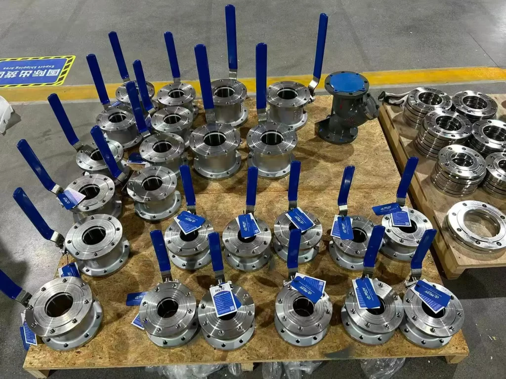
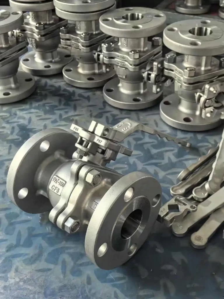
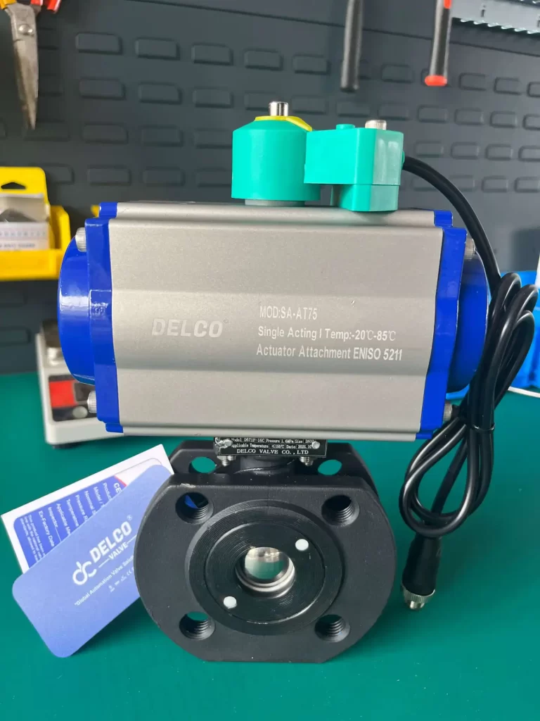
This DELCO guide walks you through those checks, from the flange gap to actuator access, so you can prepare a clearer enquiry and identify fit problems before ordering. Start with the situation that matches your project:
| Your project | Where to start |
|---|---|
| New skid with limited axial space | Evaluate a thin wafer body, then check the complete assembly and removal access |
| Replacement between fixed pipe flanges | Compare the existing interface and gap with the proposed assembly |
| Project specifies a face-to-face standard or series | Confirm that the selected model meets that exact requirement |
| Actuator or tool access is the main constraint | Compare complete configurations, including accessories and access space |
1. Look Beyond the Shorter Valve Body
If you are trying to shorten a crowded pipe run, body length is a useful starting point. Next, look above and beside the pipe: the actuator, bracket and connections may occupy the space you hoped to recover.
The two DELCO illustrations below help you see the body arrangements.
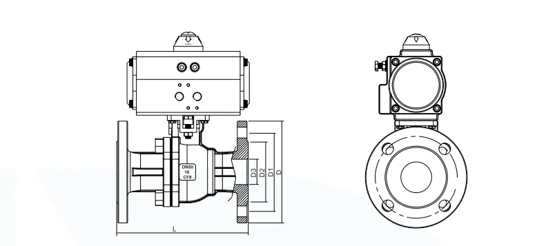
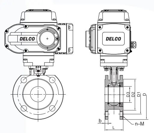
Keep two measurements separate: the valve's face-to-face length and the complete assembly's overall dimensions. Catalogue illustrations show the arrangement; an approved dimensional drawing supplies the measurements. Because these examples use different actuators, their package shapes cannot establish a body-style space saving.
When reviewing wafer ball valve dimensions, look for the model, drawing revision, units and dimension references. Also check the model's pressure–temperature rating against your medium and operating conditions. A compact shape alone does not establish service suitability.
2. Start with the Pipework You Have—or Plan to Build
Replacing an existing valve
If your pipework is already fixed, start with the space it provides. Record the distance between the mating pipe-flange sealing faces and explain how it was measured, including whether the existing valve and gaskets remain installed.
You can then compare that gap with the proposed valve's face-to-face dimension and specified gasket arrangement. Using consistent reference points helps your supplier understand the installation.
Designing a new skid
You have more flexibility while the skid is being designed. Select the valve configuration before fixing the spool dimensions, then account for fabrication tolerances and the specified gaskets. This reduces the risk of a length mismatch while leaving time to resolve actuator and maintenance access.
Details to include in either enquiry
- Nominal size and required internal bore
- Flange standard, size and pressure rating
- Flange-facing type and specified gaskets
- Bolt-circle diameter, hole count and hole or thread dimensions
- Pipe alignment, support positions and restrictions on movement
Both body styles need compatible mating flanges, suitable sealing surfaces and the specified gasket and bolting procedure. Checking the existing flange faces early helps identify connection problems before you commit to a replacement.
The bolt pattern may match while the assembled length does not. A thinner replacement can therefore leave an axial gap between otherwise compatible pipe flanges.
If that happens, have the piping arrangement reviewed before ordering. Extra gaskets or forcing the pipework into position should not be treated as a fit solution.
3. Leave Room to Connect and Operate the Assembly
Imagine the valve in place with neighbouring pipes and the skid frame installed. Can the installer still insert each bolt, reach it with a tool and connect the actuator? These details help determine whether a compact layout is practical.
Ask for the fastening arrangement and specifications, including length and any required thread engagement. Through-studs and bolts engaging threaded body holes can need different access paths.
Review the assembly in both side and end views. For support and handling plans, use its documented mass and centre of gravity, including the actuator, bracket and fitted accessories.
| Check area | Question to resolve |
|---|---|
| Bolt insertion | Can each fastener enter with neighbouring equipment in place? |
| Tightening access | Can the required tool reach every fastener? |
| Bolt withdrawal | Can fasteners be removed without an obstructing pipe or frame member? |
| Assembly height and width | Do the actuator, bracket and accessories clear surrounding equipment? |
| Cable or air connections | Can fittings be installed and cables or tubing routed appropriately? |
| Manual operation | Is the manual mechanism accessible throughout its movement? |
| Service access | Can covers, mounting hardware and serviceable components be reached? |
These checks help you judge whether a compact actuated ball valve will be usable within your layout. Include the movement of any lever or manual override as well as the fixed equipment outline. The actuator output turns while its housing remains stationary; the manual mechanism has its own access requirements.
If actuator size is the limiting factor, review valve torque requirements and actuator selection together. A thin valve body alone does not justify a smaller actuator. Our low-torque ball valve guide covers that selection question.
For electric control and wiring requirements, see the motorized ball valve selection guide.
4. Plan for the Day the Valve Needs Replacing
A valve that fits during skid assembly may be harder to reach once everything around it is installed. Planning the removal route now helps you spot obstacles before the layout is fixed.
Following the selected equipment's instructions, establish how the assembly will be supported and withdrawn after safe isolation and depressurisation.
Identify which connections must be released, the separation needed at sealing interfaces, and the withdrawal space for fasteners and the valve. Releasing one flange joint does not establish that the complete valve can be removed. If you plan to remove the actuator first, confirm that the selected arrangement permits it and provides sufficient access.
| What you find | What to do next |
|---|---|
| Interface, assembled dimensions and removal access are confirmed | Proceed to final drawing approval |
| Flange details match, but the fixed gap does not | Review piping changes before treating it as a replacement |
| Body fits, but actuator or connections clash | Revise the configuration or layout |
| Assembly fits, but fasteners cannot be withdrawn | Resolve maintenance access |
| Valve cannot leave the pipe run | Review the removal path |
| Critical dimensions are missing | Request the missing information and keep those items pending |
If a dimension is missing, mark it Pending and request confirmation before ordering. You can continue preparing the enquiry while keeping assumptions separate from approved information.
5. Turn Your Fit Check into a Clear Purchase Enquiry
You do not need every dimension ready to start an enquiry. When requesting a DELCO configuration, send the drawings and site information you already have, and mark the remaining items as pending.
Use the sheet below to organise your requirements and request a drawing of the proposed valve, actuator and mounting arrangement. Keep the drawing reference beside each confirmed item so the purchasing and installation teams work from the same information.Installation Compatibility Checklist: Thin vs Flanged Ball Valves
| Confirmation Item | Requirement / Drawing Reference |
|---|---|
| Valve Type & Drawing | Confirm valve type, model, drawing revision, and units. |
| Operating Conditions | Verify medium, operating pressure, and temperature. |
| Nominal Size & Bore | Confirm DN/NPS and full-bore or reduced-bore requirements. |
| Pressure–Temperature Rating | Verify the valve rating against actual service conditions. |
| Flange Compatibility | Confirm mating flange standard, pressure class, and facing. |
| Face-to-Face Dimensions | Compare available installation gap with valve dimensions. |
| Gasket & Sealing Requirements | Verify gasket compatibility and sealing surface requirements. |
| Bolting Arrangement | Confirm bolt dimensions, configuration, and tool access. |
| Actuator & Clearance | Check actuator orientation, overall dimensions, and operating space. |
| Piping & Support | Verify connection access, pipe alignment, and support. |
| Removal & Lifting Access | Confirm maintenance clearance and safe removal arrangements. |
The aim is to choose an assembly that works for your pipework and leaves practical access for the people installing and maintaining it. Once the outstanding items are resolved, you have a clearer basis for choosing between wafer and flanged ball valves.
Not sure which dimensions to send? Start your DELCO enquiry with an existing drawing or a marked-up sketch, photos of the valve location and your operating conditions. Add your company, industry, quantity and target delivery date, plus any procurement specification you need to meet. Photos help explain access restrictions; final fit confirmation still requires dimensions. You can also browse our electric wafer thin ball valve range to describe the configuration you are considering.
Frequently Asked Questions
It may be possible, but start with your existing flange gap and connection details. The selected valve must also meet the service requirements and leave enough room for its actuator, fasteners and removal. Matching DN and flange drilling alone does not confirm a direct replacement.
Not necessarily. A shorter body may leave a gap rather than create usable space. Compare the existing flange gap with the valve length and specified gaskets. If they do not match, arrange a piping review before ordering instead of treating additional gaskets or forced pipe movement as a solution.
You may be able to, but a matching mounting interface is only the starting point. Ask the supplier to confirm the drive connection, required torque, operating travel and compatibility with the valve's limits. Include the mounting arrangement and resulting assembly dimensions in the review before deciding to reuse it.
Use the gasket type, dimensions and mating-flange facing specified for your selected model and service conditions. If you are replacing another valve, check the new requirements rather than assuming the previous gasket specification still applies. Wafer ball valves do not all use one universal sealing arrangement.
The answer depends on the model and layout, not DN alone. Start with the fastener withdrawal path, separation at the sealing interfaces and the direction the supported assembly will leave the pipework. The model's drawings and maintenance instructions should establish the required space, including any permitted actuator-removal step.
Share on Social:


- PREV: Pneumatic Butterfly Valve: Types, Working Principle & Complete Selection Guide
- NEXT: Not NEXT