



 Home /
 Fail-Safe Electric Actuated Valves: What Happens on Power Loss
Water Treatment Valve Selection Guide: Engineering Reliability and Compliance
Sep 28, 2026
Globe Control Valve: Working Principle, Types & Selection Guide
Sep 24, 2026

Valve Materials for Abrasive Slurry: Ceramic, Tungsten Carbide & Lined
Sep 22, 2026
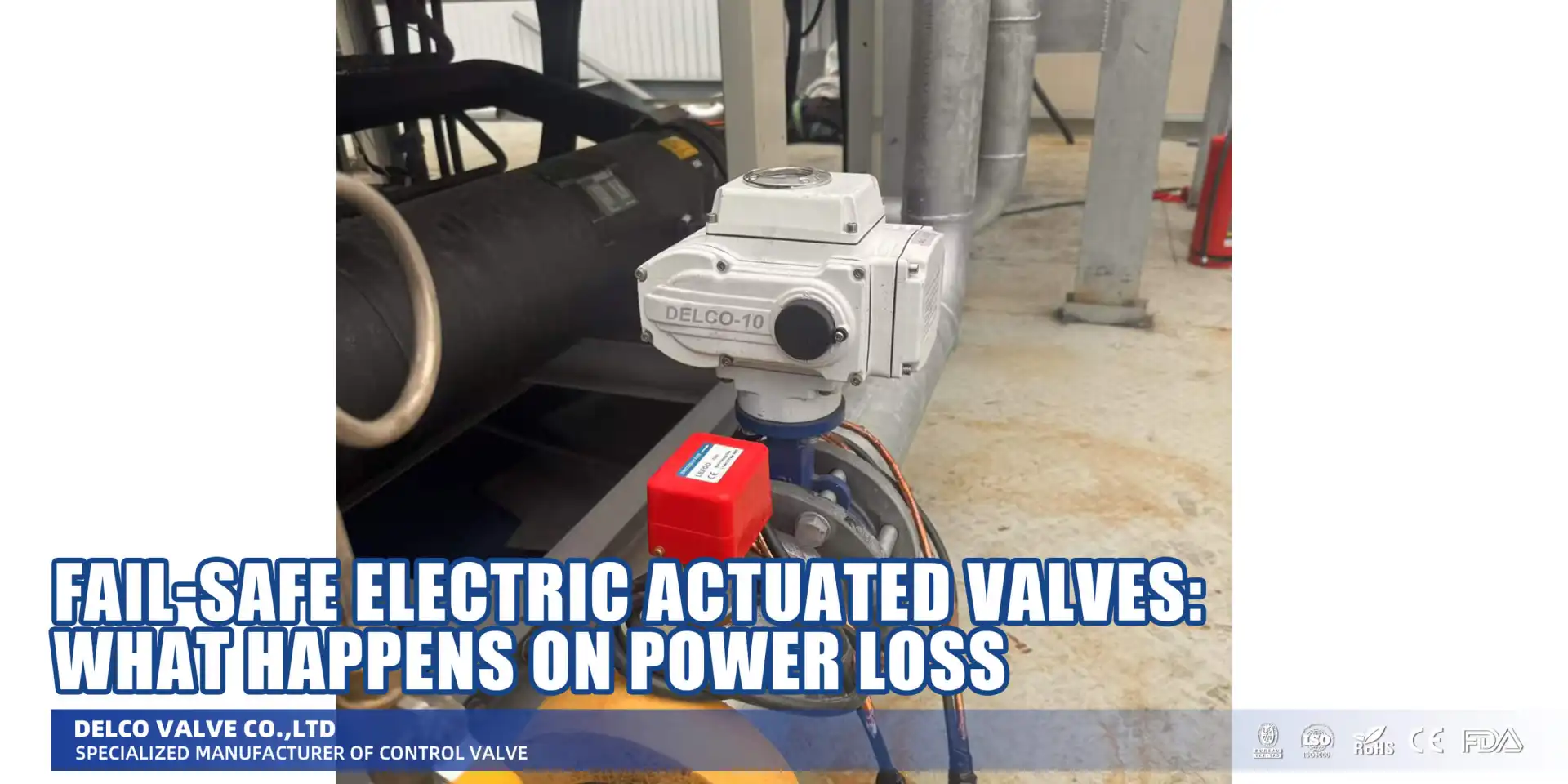
Fail-Safe Electric Actuated Valves: What Happens on Power Loss
Sep 17, 2026
1. Introduction: The Critical Nature of Fail-Safe Systems
Picture this scenario: It is 2:00 AM at a large-scale chemical processing facility. The plant is running at full capacity, processing volatile hydrocarbons under high pressure and temperature. Suddenly, a severe electrical storm sweeps through the area, striking the main power grid and taking out both the primary power lines and the immediate transformer banks. The facility goes completely dark. Pumps stop, compressors halt, and automated control systems lose their primary power source.
In this critical moment, the safety of the entire plant relies on a single, vital question: What happens when an electric actuator loses power?
Without power, a standard electric valve actuator will simply stop in its current position. In a process involving highly reactive chemicals or high-pressure steam, a valve left in the "open" position during a power failure could lead to disastrous consequences—overflows, catastrophic pressure buildup, fires, or explosions. This is exactly where fail-safe electric actuated valves become the most important components in your piping infrastructure.
A fail-safe electric actuator is engineered to automatically drive the valve to a predetermined, safe position (either fully closed, fully open, or locked in place) the instant power is lost. For process engineers, automation engineers, and safety personnel, understanding the nuanced behavior of a fail-safe valve is not just a matter of operational efficiency; it is a fundamental requirement for plant safety and environmental protection.
In this comprehensive guide, we will explore the engineering mechanics behind fail-safe electric actuators, compare the various fail-safe mechanisms available, contrast them with traditional pneumatic options, and provide a detailed framework for selecting the correct fail-safe action for your specific application.
2. What Is a Fail-Safe Valve?
A fail-safe valve is a specialized control or isolation valve equipped with an actuator designed to return to a mathematically and operationally "safe" state in the event of an energy supply failure. The "energy supply" can refer to electrical power, compressed air, or hydraulic fluid, depending on the actuator type. In the context of electric actuated valves, the failure mode is almost exclusively a loss of electrical power (or sometimes a loss of the control signal, though this is handled differently by intelligent actuators).
The core philosophy behind any fail-safe system is risk mitigation. When the system can no longer actively control the process, it must passively default to a state that minimizes harm to personnel, prevents damage to equipment, and avoids environmental contamination.
When discussing fail-safe valves, engineers generally classify them into three distinct fail-safe positions. Selecting the right position requires a deep understanding of the specific process fluid, system pressure, and upstream/downstream dynamics.
Fail-Close (FC) / Normally Closed (NC)
A fail-close valve is designed to automatically shut completely when power is lost. This is by far the most common fail-safe configuration in industrial applications.
- The Objective: To stop the flow of hazardous, flammable, or expensive media.
- Typical Applications: Fuel supply lines to boilers, chemical injection systems, steam isolation valves, and hazardous gas lines. If power is lost, you want the fuel or hazardous chemical to stop flowing immediately to prevent a fire or toxic leak.
Fail-Open (FO) / Normally Open (NO)
A fail-open valve is designed to automatically spring to the fully 100% open position upon loss of power.
- The Objective: To relieve pressure, supply cooling media, or dump a process to a safe containment area.
- Typical Applications: Cooling water supply lines to a reactor, fire deluge systems, and emergency pressure relief lines. If a chemical reactor loses power and the agitators stop, the reaction might run away and generate massive heat. In this case, the cooling water valve MUST fail-open to flood the jacket and cool the reactor, preventing an explosion.
Fail-in-Place (FIP) / Fail-Lock
A Fail-in-Place (also known as Fail-Last or Fail-Lock) configuration means that upon power loss, the actuator immediately locks the valve in its current exact position. It neither opens nor closes, but remains completely static.
- The Objective: To maintain the current system equilibrium and prevent sudden surges or drops in flow that could disrupt a delicate process when power returns.
- Typical Applications: HVAC chilled water systems, certain mixing processes, and continuous blending operations where a sudden change in valve position would ruin the batch or cause severe water hammer.
For further details on how these configurations integrate with specific valve bodies, you can explore DELCO electric actuated valves.
3. How Fail-Safe Works in Electric Actuators
Historically, achieving a reliable fail-safe action was the primary reason engineers chose pneumatic actuators over electric ones. A pneumatic actuator easily achieves fail-safe operation by placing a large mechanical spring inside the casing; when air pressure is lost, the spring simply pushes the valve closed or open.
However, modern advancements in electrical engineering and battery technology have revolutionized fail-safe electric actuators. Today, electric actuators can achieve highly reliable fail-safe operations without the need for a plant-wide compressed air system. There are three primary mechanisms by which an electric actuator achieves fail-safe operation: Spring-Return, Battery/Capacitor Backup, and Mechanical Locking.
A. Spring-Return Mechanism (Electro-Mechanical)
The spring-return electric actuator closely mimics the reliable design of its pneumatic cousin. Inside the actuator housing, alongside the electric motor and gear train, sits a robust, heavy-duty mechanical spring (often a clock spring or a linear coil spring, depending on the valve type).
- How it works during normal operation: When electrical power is supplied, the electric motor drives the valve to the desired position (open or closed). During this driving process, the motor is simultaneously compressing or winding the mechanical spring, storing potential energy. An electro-magnetic clutch or holding brake engages to keep the valve in position, preventing the spring from releasing its energy.
- What happens when an electric actuator loses power: The instant power fails, the electro-magnetic clutch disengages. With nothing holding it back, the massive potential energy stored in the mechanical spring is instantly released. The spring rapidly unwinds or expands, driving the gear train in reverse and forcing the valve to its designated fail-safe position (open or closed) purely through mechanical force.
- Pros: Highly reliable, purely mechanical failsafe (no batteries to degrade), excellent for high-criticality safety systems.
- Cons: Actuators are larger, heavier, and more expensive due to the massive motor torque required to overcome the spring during normal operation.
B. Battery Backup / Supercapacitor System (Electronic Fail-Safe)
Instead of relying on mechanical springs, modern intelligent actuators often use an integrated, uninterruptible power supply (UPS) internally. This takes the form of high-density lithium-ion battery packs or, increasingly, industrial-grade supercapacitors.
- How it works during normal operation: The primary electrical power line operates the valve motor and simultaneously trickles charge into the internal battery pack or supercapacitor bank, ensuring they are always at 100% capacity.
- What happens when an electric actuator loses power: An internal logic board detects the voltage drop on the main power line. It instantly switches the power source to the fully charged internal battery or capacitors. The actuator then uses this stored electrical energy to power the motor and drive the valve to the pre-programmed fail-safe position.
- Pros: Actuators are much smaller and lighter than spring-return models. The fail-safe direction (open or closed) can often be changed in the field via a software setting, offering immense flexibility.
- Cons: Batteries degrade over time and require a strict maintenance schedule. Supercapacitors have a longer lifespan but are sensitive to extreme ambient temperatures.
C. Mechanical Lock (Worm-Gear Self-Locking)
For Fail-in-Place requirements, electric actuators utilize a specific type of gear train, almost universally a worm gear mechanism.
- How it works: A worm gear consists of a threaded worm (driven by the motor) mating with a worm wheel (connected to the valve stem). Due to the friction and the angle of the gear teeth, a worm gear is inherently self-locking. While the motor can easily turn the worm to rotate the wheel, any reverse force applied from the valve to the wheel cannot turn the worm.
- What happens when an electric actuator loses power: The motor stops. Because of the self-locking nature of the worm gear, the valve is physically incapable of moving, regardless of the pipeline pressure pushing against the valve disc. It stays locked exactly where it was at the moment of power loss.
Comparison Table: Fail-Safe Mechanisms in Electric Actuators
| Feature / Aspect | Spring-Return Electric | Battery / Supercapacitor | Mechanical Lock (Fail-In-Place) |
|---|---|---|---|
| Fail-Safe Source | Mechanical Potential Energy | Stored Electrical Energy | Friction / Gear Geometry |
| Reliability | Very High (Mechanical) | High (Requires battery maintenance) | Very High (Inherent to gears) |
| Actuator Size/Weight | Large & Heavy | Compact & Lightweight | Compact |
| Fail Direction | Fixed (Hardwired/Mechanical) | Field-Programmable (Open/Close) | Static (Stays in place) |
| Maintenance Need | Low (Occasional spring check) | Medium (Battery replacement cycle) | Low (Standard gear lubrication) |
| Cost | Highest (Heavy-duty motors needed) | Moderate | Lowest (Standard electric actuator) |
4. Fail-Safe Electric vs. Fail-Safe Pneumatic Actuators
Historically, the gold standard for fail-safe valves was the pneumatic spring-return actuator. If you needed a fail-close valve, you installed a pneumatic actuator because compressed air was the industry norm. However, modern fail-safe electric actuators have closed the performance gap and offer compelling advantages in specific scenarios.
Understanding when to specify a fail-safe electric valve over a pneumatic one is a critical skill for process engineers.
Fail-Safe Pneumatic Actuators
Pneumatic actuators use compressed air to push a piston or diaphragm against a heavy spring. When air pressure is lost (or vented via a solenoid valve), the spring forces the valve shut or open. Advantages:
- Extremely fast acting: Pneumatic actuators can close large valves in a fraction of a second.
- Inherent fail-safe: The mechanical spring design is simple, robust, and universally trusted for Safety Instrumented Systems (SIS).
- Cost-effective per unit: The actuator itself is relatively inexpensive.
Disadvantages:
- Requires compressed air infrastructure: You need compressors, air dryers, filters, and extensive tubing networks. This infrastructure is expensive to install and heavily prone to leaks (wasted energy).
- Control limitations: While smart positioners exist, pneumatic systems can suffer from hysteresis and are generally less precise than high-end electric stepper motors.
Fail-Safe Electric Actuators
Electric actuators use an electric motor and gear train, supplemented by a spring or battery for fail-safe operation. Advantages:
- No air supply needed: Ideal for remote locations, tank farms, pipelines, or clean rooms where running compressed air lines is impractical, expensive, or unsanitary.
- High precision and intelligent control: Electric actuators offer unmatched control precision (perfect for globe control valves). They integrate seamlessly with DCS/PLC systems, providing rich diagnostic data (torque profiles, cycle counts, health monitoring) via protocols like HART, Modbus, or Profibus.
- Energy efficient: They only consume power when moving, whereas pneumatic systems constantly bleed air and require compressor energy.
Disadvantages:
- Slower operating speeds: Electric actuators generally move slower than pneumatic ones, which can be a drawback if a sub-second emergency shutdown is required.
- Higher initial cost: A fail-safe electric actuator (especially spring-return) represents a higher upfront capital investment per unit.
The Verdict: If your facility already has a massive, well-maintained compressed air system, pneumatic valves remain a solid choice for rapid emergency shutdown. However, for precise control applications, remote installations, or modern facilities aiming to reduce their carbon footprint by eliminating compressed air leaks, fail-safe electric actuators are the superior, modern choice. You can find excellent examples of these modern systems in DELCO electric globe valves.
5. How to Determine the Right Fail-Safe Action
Choosing whether a valve should be Fail-Open, Fail-Close, or Fail-in-Place is arguably the most critical engineering decision in the valve specification process. An incorrect choice can turn a benign power outage into a major safety incident.
The decision is governed by a rigorous Risk Assessment Approach, often formalized through Hazard and Operability Studies (HAZOP) and the assignment of a Safety Integrity Level (SIL).
The Risk Assessment Approach
Engineers must ask a series of "What If" questions centered around the loss of power:
- What is the media? Is it flammable, toxic, expensive, or benign (like water)?
- What happens downstream if flow continues? Will a tank overflow? Will a downstream pipe overpressurize and burst?
- What happens downstream if flow stops? Will a cooling system fail, causing a reactor to overheat? Will a pump run dry and destroy its seals?
The guiding principle is always to select the state that brings the process to its lowest possible energy, safest pressure, and least hazardous condition.
Real-World Application Examples
When to Choose Fail-Close (FC) / Normally Closed:
- Fuel Gas / Oil Supply Lines: If a boiler or furnace loses power, the combustion air fans will stop. If fuel continues to flow into the hot combustion chamber without air, it creates an explosive mixture. The fuel valve MUST fail-close.
- Hazardous Chemical Feed: In a blending process, if the agitator loses power, pumping in highly reactive chemicals will cause localized concentration and potential runaway reactions. The chemical feed valves must fail-close.
- Steam Isolation: High-pressure steam lines should fail-close to prevent uncontrolled heating of downstream processes or dangerous steam releases.
When to Choose Fail-Open (FO) / Normally Open:
- Reactor Cooling Water: As mentioned earlier, exothermic reactions need constant cooling. If power fails, the cooling water valve must fail-open to ensure continuous cooling flow to prevent an explosion.
- Pressure Relief Systems: Flare lines, vent lines, and bypass valves intended to relieve over-pressure scenarios must fail-open to ensure the system can safely depressurize during a total power blackout.
- Fire Suppression Water: Deluge systems rely on fail-open valves to ensure water reaches the hazard zone even if the electrical grid is destroyed by the fire.
When to Choose Fail-in-Place (FIP):
- HVAC Systems: In commercial cooling towers or large chilled water loops, sudden valve movements during a brief power flicker can cause severe hydraulic shock (water hammer) which can rupture massive pipes. Failing in place maintains system stability until power is restored.
- Blending Ratios: If two benign ingredients are being blended at a precise 50/50 ratio, having one valve fail-close and the other fail-open would ruin the batch. Failing in place preserves the ratio for when the process resumes.
Safety Integrity Level (SIL) Considerations
For highly critical processes, fail-safe valves are integrated into a Safety Instrumented System (SIS). These systems are rated by SIL (Safety Integrity Level), ranging from SIL 1 (lowest risk reduction) to SIL 4 (highest risk reduction).
When specifying a fail-safe electric valve for a SIL-rated loop, the actuator and valve combination must be rigorously tested and certified by third-party agencies (like exida or TÜV) to guarantee a specific Probability of Failure on Demand (PFD). Spring-return electric actuators are heavily favored in SIL 2 and SIL 3 applications due to their deterministic, mechanical fail-safe mechanism.
6. DELCO Fail-Safe Electric Actuated Valve Features
At DELCO Valves, we engineer industrial valve solutions designed for the most demanding environments. Our range of fail-safe electric actuated valves integrates robust mechanical engineering with cutting-edge digital intelligence, ensuring your processes remain safe and efficient.
Whether you are specifying an electric butterfly valve for water treatment or a high-pressure electric globe valve for steam control, our fail-safe actuators offer premium features:
- Intelligent Digital Actuators: DELCO electric actuators feature built-in microprocessors that provide continuous self-diagnostics. They monitor motor temperature, voltage fluctuations, and operational anomalies, alerting your DCS before a failure occurs.
- Precision Torque Monitoring: Our actuators continuously measure the torque required to move the valve. An unexpected spike in torque can indicate a sticky valve stem, scaling on the valve seat, or foreign debris. This allows for predictive maintenance rather than reactive repair.
- 4-20mA & HART Communication: For modulating control applications, our actuators accept standard 4-20mA analog control signals and provide continuous 4-20mA position feedback. HART protocol capability allows for rich digital communication and remote configuration over existing analog wiring.
- High-Visibility LCD Displays: Local configuration and status monitoring are made easy with high-contrast, non-intrusive LCD screens, allowing operators to check valve status, fault codes, and position percentages without opening the explosion-proof enclosure.
- Manual Override Handwheels: Every DELCO fail-safe electric actuator is equipped with a declutchable manual override handwheel. In the event of a total system failure (power loss AND battery/spring failure), operators can physically engage the handwheel to manually crank the valve to a safe position, ensuring ultimate mechanical redundancy.
- Robust Enclosures: Designed for harsh environments, our enclosures meet IP67/IP68 standards for water and dust ingress, and explosion-proof (Ex d) certifications are available for hazardous ATEX/IECEx zones.
7. Installation & Testing Requirements
A fail-safe electric valve is only as reliable as its installation and maintenance. Proper commissioning is vital.
Installation Best Practices
- Orientation: Pay strict attention to the manufacturer's orientation guidelines. While many electric actuators can be mounted in any position, heavy spring-return actuators often require vertical mounting to prevent uneven wear on the internal gearings and bearings due to the immense weight of the spring housing.
- Wiring Integrity: Ensure that the power supply wiring is appropriately sized for the inrush current of the electric motor. For battery-backup systems, ensure the permanent power supply is stable to keep the internal UPS charged.
- Environmental Protection: While the actuators are weatherproof, installing sun shields in extreme desert environments can prevent LCD degradation and protect battery chemistries from overheating.
Commissioning and Proof Testing
Fail-safe valves are inactive safety devices—they sit quietly waiting for an emergency. Therefore, they must be regularly tested to ensure they will work when called upon. This is known as Proof Testing.
- Partial Stroke Testing (PST): Intelligent DELCO electric actuators can be programmed to perform a Partial Stroke Test. The actuator momentarily moves the valve just 10-15% of its travel and then returns to the normal position. This proves that the motor, gears, and valve stem are not seized, all without interrupting the actual process flow.
- Full Power-Loss Simulation: During planned plant shutdowns or turnarounds, a full functional test must be performed. Power to the actuator is physically disconnected at the breaker to verify that the spring-return or battery-backup system engages smoothly and drives the valve to the correct position within the required time frame.
- Battery Maintenance: For battery-based electronic fail-safe systems, maintenance protocols must dictate battery replacement every 3 to 5 years, regardless of apparent health, to guarantee emergency capacity.
8. Frequently Asked Questions (FAQ)
1. How fast does a spring-return electric actuator close a valve? While slightly slower than pneumatic systems, modern spring-return electric actuators are quite fast. Depending on the valve size and actuator torque, they can typically drive a valve to the fail-safe position in 3 to 10 seconds. Highly specialized units can achieve 1-second closures for smaller valves.
2. Can the fail-safe action (Fail-Open vs. Fail-Close) be changed in the field? It depends on the technology. For mechanical spring-return actuators, changing the fail direction usually requires physically disassembling the actuator and reversing the spring module or gear train—a complex task. However, for electronic battery-backup actuators, the fail-safe direction is often just a software parameter that can be easily reprogrammed in the field via the local LCD menu.
3. What is the lifespan of the battery in an electronic fail-safe actuator? Industrial-grade lithium-ion battery packs typically have a reliable lifespan of 3 to 5 years, heavily dependent on ambient temperature (excessive heat degrades batteries quickly). Systems using supercapacitors can last 10 years or more, offering a near-maintenance-free electronic fail-safe solution.
4. Are electric fail-safe valves SIL certified? Yes. Many high-quality spring-return electric actuators are certified to SIL 2 or SIL 3 standards by agencies like exida or TÜV Rheinland. Battery-backup systems can also achieve SIL ratings, though they often require more stringent diagnostic monitoring and maintenance schedules to maintain their Safety Integrity Level.
5. Does a fail-safe electric actuator still have a manual override? Yes. Almost all industrial fail-safe electric actuators feature a declutchable manual handwheel. Even if power is lost and the fail-safe mechanism (spring or battery) has already actuated the valve, an operator can engage the manual clutch to physically overcome the spring or gears and reposition the valve by hand if necessary.
9. Conclusion and Next Steps
In industrial fluid control, hoping for continuous, uninterrupted electrical power is not a strategy—it is a gamble. Fail-safe electric actuated valves are the ultimate insurance policy for your process infrastructure, ensuring that when the worst-case scenario occurs and the lights go out, your facility defaults to a safe, controlled state.
Whether you require the brute-force mechanical reliability of a spring-return actuator or the compact, intelligent flexibility of a supercapacitor backup system, understanding what happens when an electric actuator loses power empowers you to design safer, more resilient piping systems. By carefully evaluating your media, downstream risks, and SIL requirements, you can specify the perfect Fail-Close, Fail-Open, or Fail-in-Place solution.
At DELCO Valves, we combine decades of metallurgical expertise with advanced digital actuation technology to deliver valves you can trust in your most critical applications.
Ready to upgrade your plant's safety infrastructure?
- Explore our comprehensive catalog: Browse our full range of DELCO electric actuated valves to find the perfect fit for your application.
- Need technical guidance? Contact our engineering team at inquiry@delcofluid.com for assistance with sizing, SIL certification, or custom valve configurations.
- Request a Quote: Specify your required fail-safe parameters and get a detailed proposal from our valve experts today.
Share on Social:


Contact Us
In This Article
Water Treatment Valve Selection Guide: Engineering Reliability and Compliance
Sep 28, 2026
Globe Control Valve: Working Principle, Types & Selection Guide
Sep 24, 2026
Valve Materials for Abrasive Slurry: Ceramic, Tungsten Carbide & Lined
Sep 22, 2026
Fail-Safe Electric Actuated Valves: What Happens on Power Loss
Sep 17, 2026