



 Home /
Electric Gate Valve Actuator Sizing Guide: Stem Travel, Thrust & Selection Checklist



Electric gate valve actuator sizing is more than picking a torque number from a catalogue. The valve and actuator must be checked as a complete assembly — pipe size, pressure class and supply voltage define part of the specification, but the stem mechanism, operating loads, travel, speed and mechanical connection determine whether the assembly will actually work.
For procurement teams, EPC contractors and equipment integrators, the practical question is:
Can this actuator operate this valve under the specified conditions without exceeding the assembly's mechanical limits?
Follow these six steps to review the proposed configuration before ordering.
Step 1. Confirm the Valve and Operating Conditions
Start with the selected valve's data and the conditions under which it must open and close.
| Information Required | What to Confirm |
|---|---|
| Process conditions | Medium, temperature and maximum differential pressure during operation |
| Valve construction | Model, size, pressure class, seat design and stem arrangement |
| Operating loads | Opening, running and closing torque or thrust, with stated conditions |
| Movement | Actual gate travel, thread lead and required revolutions |
| Actuation requirements | Operating time, frequency, power supply and control requirements |
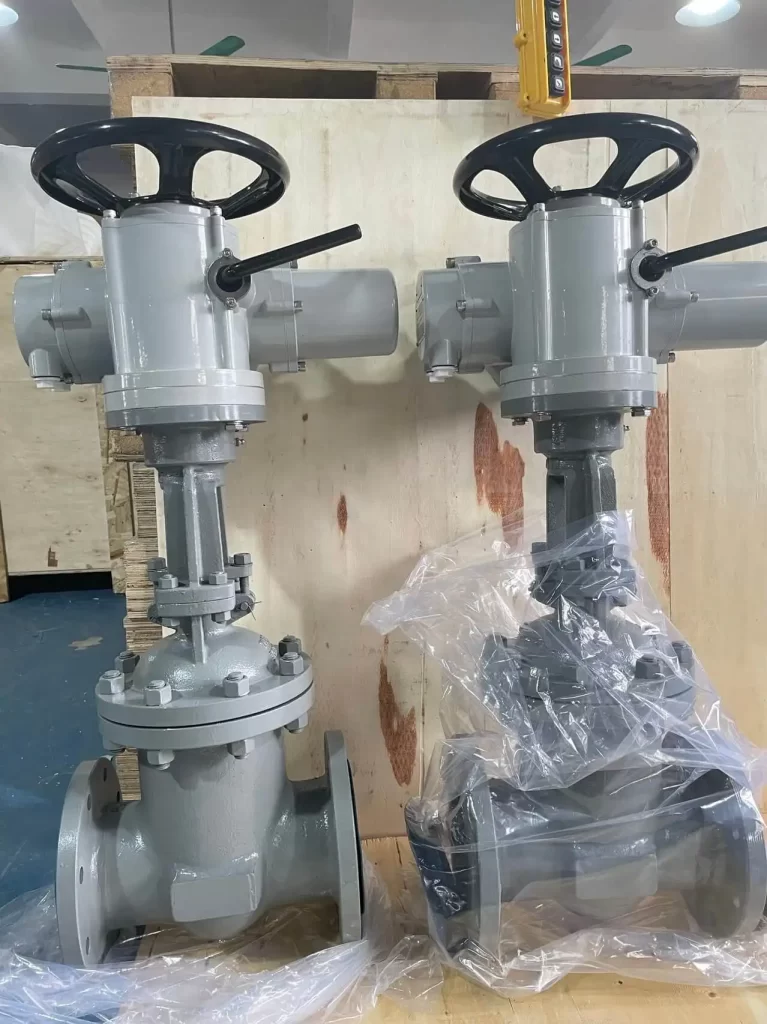
Key Distinctions
Pressure class ≠ operating differential pressure. Pressure class relates to the valve's pressure-temperature rating. Differential pressure (ΔP) is the pressure difference across the gate during operation — this is what drives the operating load.
Ask the valve supplier:
- Are the load figures calculated or measured?
- Which operating conditions do they represent?
- Do they already include a selection margin?
Use Data for the Actual Construction
A resilient-seated waterworks gate valve and a metal-seated industrial wedge valve should not share an assumed torque requirement simply because they have the same DN. Use data specific to the actual valve model and construction.
For an existing valve, include its condition, maintenance history and any modifications in the assessment.
Step 2. Identify Stem Motion and Thrust Path
A multi-turn gate valve actuator provides rotary output. The threaded mechanism converts relative rotation into linear gate movement. The stem arrangement determines how force is transmitted — and where it must be supported.
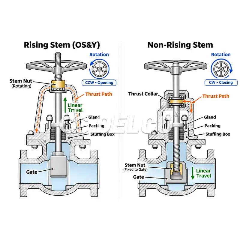
Rising, Non-Rotating Stem
The actuator rotates a stem nut, which advances the stem and gate linearly. Check:
- Through-bore clearance for the rising stem
- Stem protection tube
- Clearance at the highest stem position (full open)
Non-Rising Stem
The stem rotates while the gate travels along the internal thread. External height requirements are reduced, but the axial operating force still needs a defined support path.
What to Confirm from the Valve Drawing
| Item | Why It Matters |
|---|---|
| Which component rotates | Determines drive connection type |
| Which component moves axially | Determines clearance requirements |
| Where the stem thread engages | Defines the force conversion point |
| Which bearings or structures carry axial thrust | Identifies the load path |
Depending on the design, thrust may be carried within the valve body, an actuator thrust base, a gearbox or another support arrangement.
Torque capability and thrust-bearing capacity must be checked separately. A suitable rotary output does not establish that the proposed mounting arrangement can carry the axial load.
Step 3. Calculate Travel, Turns and Operating Time
Use the actual travel and thread lead to determine the required revolutions and travel time.
Thread Lead vs Pitch
- Pitch = axial spacing between adjacent thread forms
- Lead = axial movement per one complete revolution
For a multi-start thread:
Lead=Pitch×Number of starts
Required Revolutions
For a direct screw-drive arrangement:
Required revolutions=LeadTravel
Operating Time
At constant speed:
Travel time (seconds)=Drive speed (rpm)60×Required revolutions
The dimensions and speed must refer to the same mechanism. If an intermediate gearbox is present, use the speed at the valve drive, not at the actuator output.
For reference, Global Supply Line's sizing worksheet similarly links travel speed, stem lead and required rpm: Gate and globe valve sizing worksheet (PDF)
Worked Example
| Parameter | Value |
|---|---|
| Gate travel | 240 mm |
| Thread lead | 6 mm/rev |
| Valve-drive speed | 24 rpm |
Required revolutions:
240÷6=40 revolutions
Theoretical travel time:
2460×40=100 seconds
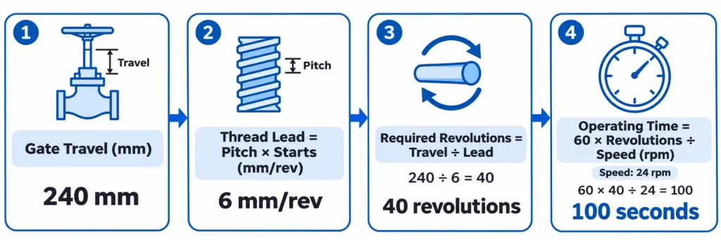
This verifies the basic movement requirement. The final operating turns and time must also reflect:
- Valve seating movement and endpoint settings
- Actual drive behaviour under load
- Configurable turn range in the actuator's travel/position system
For water pipelines, the specified closing time must also satisfy the project's hydraulic transient (water hammer) requirements.
Need Help With These Calculations?
Send us your valve data — we'll run the sizing calculations for you and return a configuration summary with the matched actuator model, calculated travel time and interface check.
→ Request a Free Sizing Review | Or email your valve schedule to inquiry@delcofluid.com
Step 4. Verify Operating Loads and Mechanical Limits
Gate valve actuator sizing requires both sufficient operating capability and acceptable loads throughout the connected assembly.
Check Opening, Running and Closing Loads
- Torque = rotational moment, expressed in N·m
- Thrust = axial force, expressed in N or kN
Their relationship depends on the stem thread geometry, friction, bearings and drive arrangement. The same actuator torque can produce different stem thrust in different assemblies.
Obtain the applicable requirements for each stage:
| Stage | What Happens |
|---|---|
| Opening / unseating | Releasing the gate under the specified differential pressure |
| Running | Moving through the stroke, including any governing intermediate position |
| Closing / seating | Reaching the required closed condition and seating load |
Do not assume one stage always governs. Record the conditions and margin associated with each load value.
Check What the Assembly Can Withstand
These are different quantities — distinguish them carefully:
- Required operating loads — what the valve needs
- Actuator rated capability — what the actuator is designed to deliver
- Protection / torque-switch settings — where the actuator stops or limits output
- Maximum / stall output — the highest output the actuator can produce
- Allowable component loads — what the stem, nut, bearings and mounting parts can withstand
An oversized actuator can overload and damage a connected component — even when its normal operating capability appears adequate. Always check stall torque/thrust against component limits.
Review the stem, nut, bearings, mounting parts and any gearbox.
Step 5. Verify Interface Compatibility
A matching mounting flange establishes only part of mechanical compatibility. Verify the complete mechanical connection from the actuator drawing and the valve drawing.
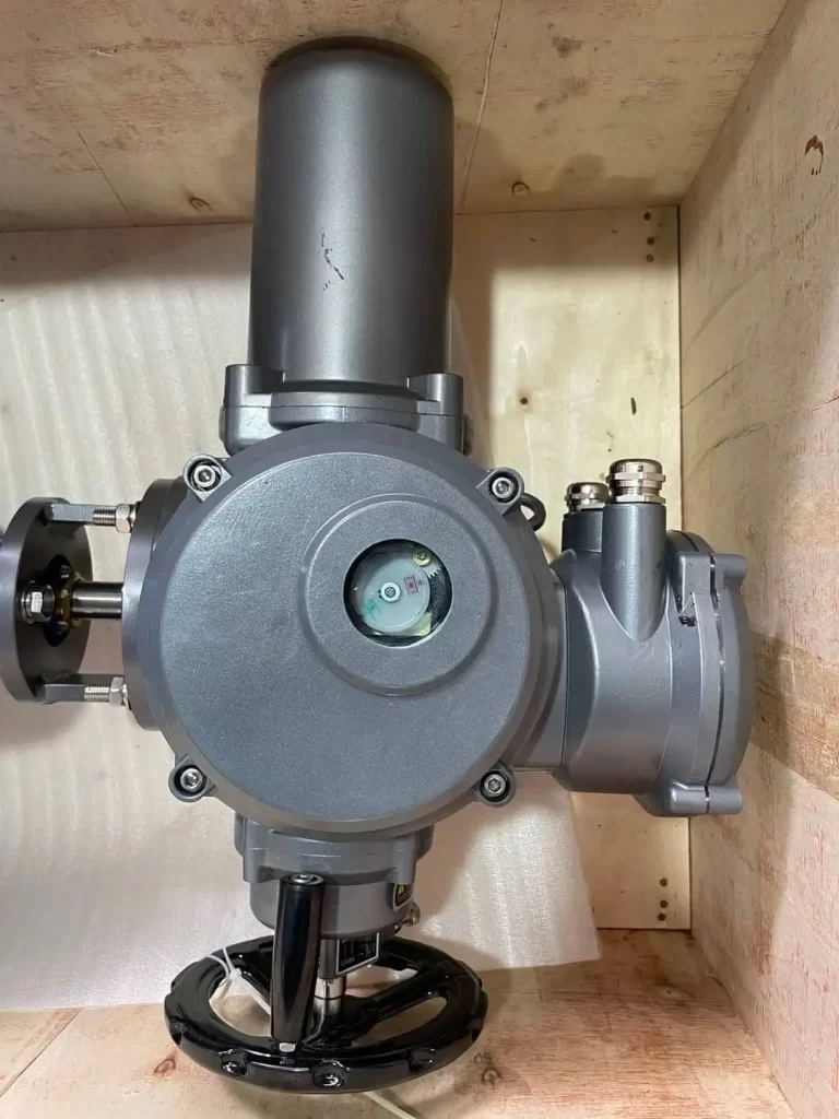
Interface Checklist
| Check Item | Details |
|---|---|
| Mounting flange | Flange dimensions, fasteners and locating features |
| Drive coupling | Drive type (square, multi-spline, etc.) and engagement dimensions |
| Stem thread | Thread form, diameter, pitch, lead, number of starts, handedness |
| Thrust support | Thrust base, bracket and gearbox arrangement |
| Direction | Opening and closing rotation direction |
| Clearance | Full-open stem clearance and maintenance access |
Reference standard: ISO 5210:2026 — covers multi-turn actuator attachment requirements, including flange and driving-component dimensions and reference torque/thrust values.
Finally, confirm the selected actuator's:
- Operating time and duty rating
- Electrical configuration (voltage, phase, frequency)
- Endpoint action (opening and closing may use different stopping methods)
Follow the specific valve and actuator instructions for endpoint configuration.
Step 6. Compare Complete Configurations Before Ordering
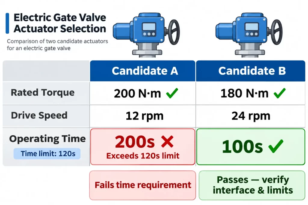
Return to the 40-revolution example from Step 3. Assume the project requires:
- Theoretical travel time: ≤ 120 seconds
- Governing drive torque: 150 N·m (including agreed margin)
Candidate Comparison
The following candidates are fictional. Stated output is assumed to apply at the specified supply and duty.
| Check | Candidate A | Candidate B |
|---|---|---|
| Rated drive torque | 200 N·m ✅ | 180 N·m ✅ |
| Valve-drive speed | 12 rpm | 24 rpm |
| Calculated travel time | 200 s ❌ | 100 s ✅ |
| Preliminary result | Meets torque; misses time | Meets both numerical checks |
Candidate A has higher rated torque but fails the operating-time requirement.
Candidate B remains a candidate — but only until its thrust support, mechanical limits, interface, travel range, duty and controls are all verified.
This comparison shows why selecting from a torque range alone is insufficient. Operating time, interface and mechanical limits must be checked together.
Pre-Order Configuration Record
Before placing the order, request a configuration record containing:
- Valve model, construction and operating conditions
- Load data, source and stated margin
- Selected actuator and gearbox (where applicable)
- Travel, turns, speed and operating time
- Mechanical interface and thrust-support drawings
- Electrical configuration and endpoint settings
- Agreed inspection and testing requirements
Define what the acceptance tests will demonstrate. An unloaded full-stroke test can verify movement, direction, indication and basic control operation. It does not establish operation against the project's maximum differential pressure.
Ready to Compare Configurations for Your Project?
Send us your valve schedule and operating conditions. We'll return a matched configuration summary — including actuator model, sizing calculations, interface verification and a documentation package — within 3 business days.
For DELCO assemblies, use the Z-Series multi-turn electric actuator as a starting point, then confirm the exact configuration against your project documents.
Frequently Asked Questions
How do I calculate gate valve actuator torque requirements?
The valve manufacturer provides torque or thrust data for a specific valve model, size, pressure class and set of operating conditions. These values are not interchangeable between different valve types or constructions. Request data that states the conditions, method (calculated or measured) and whether a margin is included.
What is the difference between torque and thrust in gate valve sizing?
Torque is the rotational moment (N·m) delivered by the actuator. Thrust is the axial force (N or kN) acting on the stem. The stem thread, friction and drive arrangement convert one into the other. The same actuator torque produces different thrust in different assemblies — both must be checked.
How do I select an actuator for a rising stem gate valve?
For a rising, non-rotating stem arrangement, the actuator rotates a stem nut that advances the stem linearly. Check the through-bore, stem protection tube and full-open clearance. Confirm that the mounting arrangement can carry the full axial thrust, not just the rotational torque.
What mounting standard applies to multi-turn gate valve actuators?
ISO 5210 defines multi-turn actuator attachment requirements, including mounting flange dimensions, driving-component geometry and reference torque/thrust values. Always verify the actual interface dimensions from the valve and actuator drawings — a matching flange alone does not establish full compatibility.
Will an electric gate valve close automatically after power loss?
Only if the assembly includes the energy source (e.g., battery, spring, supercapacitor) and control arrangement needed to perform that movement without external power. A remote close command or ESD input alone does not provide power-loss operation. Specify loss of power and loss of control signal as separate failure modes with defined actions.
How fast should an electric gate valve close?
Closing time depends on the application. Industrial process valves are sized to the operating-time requirements in the project specification. For water pipelines, closing time must also satisfy hydraulic transient analysis to prevent water hammer. There is no universal "correct" closing speed — it must be calculated for each system.
Can an oversized actuator damage a gate valve?
Yes. An oversized actuator's stall torque or thrust can exceed the allowable load of the stem, nut, bearings or mounting components, causing mechanical failure — even if its rated output appears suitable. Always check the maximum possible output against the weakest component in the assembly.
What information should I send for actuator sizing?
Provide your valve schedule (model, size, pressure class), operating conditions (medium, temperature, differential pressure), required opening and closing times, and any available valve or interface drawings. These inputs establish the basis for matching the valve, stem drive and multi-turn actuator.
Get Your Electric Gate Valve Actuator Configuration Reviewed
Send us the following — we'll provide a matched actuator recommendation with full sizing documentation:
✅ Valve schedule (model, size, pressure class)
✅ Operating conditions (medium, temperature, ΔP)
✅ Required opening and closing times
✅ Available valve or interface drawings
→ Request Configuration Review | Email: inquiry@delcofluid.com
Share on Social:


