



 Home /
Grooved Motorized Butterfly Valves: Pipe OD and Coupling Compatibility Before Ordering



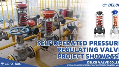
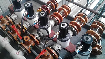
A motorized grooved butterfly valve connects to the piping system through grooved couplings and gaskets. Before ordering, the valve ends, prepared pipe ends, and selected couplings need to be checked as a complete connection.
For mechanical contractors and equipment buyers, three checks come first:
- Identify the actual pipe outside diameter and exact coupling model.
- Compare the applicable groove dimensions and service requirements.
- Confirm the complete motorized assembly fits the installation space.
This guide explains what to check, how to use a valve drawing, and which details to include in an enquiry.
1. Confirm Pipe Outside Diameter Before Selecting the Valve
DN identifies a nominal size. It is not a measurement of the pipe’s outside diameter.
An enquiry such as “DN150 grooved butterfly valve with electric actuator” is a useful starting point, but it does not fully define the connection. The supplier still needs the specified pipe OD and the requirements of the selected coupling.
For a new installation, obtain this information from the project piping specification. For replacement work, check the existing pipe documentation and coupling identification.
| Information | What to Confirm |
|---|---|
| Nominal size | The DN or NPS designation used in the project |
| Actual pipe OD | The specified outside diameter, with units |
| Pipe material | The material of the connecting pipe |
| Wall thickness | The specified thickness or pipe schedule |
| Pipe-end preparation | The applicable groove specification and preparation method |
| Coupling identification | Manufacturer, model, and size markings |
If a site measurement differs from the drawing, resolve the discrepancy before selecting the valve. Record where the measurement was taken and whether coatings or surface condition could affect the reading.
For purchasing purposes, list nominal size and actual pipe OD as separate fields. Do not select a coupling merely because its nominal size matches the valve description.
If the project has not yet selected its connection type, see Valve Connection Standards Wafer vs Lug vs Flange Guide before proceeding with the grooved-connection checks in the following sections.
2. Check the Groove Specification and Coupling Model
“Grooved” identifies a connection method, but it does not define every dimension or requirement needed for compatibility.
Descriptions such as “standard groove” or “Victaulic-style connection” should therefore be supported by the exact coupling model and its technical documentation.
Where the project specifies ANSI/AWWA C606, Grooved and Shouldered Joints, include the required edition in the enquiry. Identify the applicable groove system and confirm that the selected components meet the relevant requirements.
A standard reference alone does not confirm an unspecified valve-and-coupling combination.
| Compatibility Check | Documents to Compare |
|---|---|
| Valve-end geometry | Valve-end drawing, dimension definitions, and tolerances |
| Prepared pipe ends | Pipe specification and applicable groove-preparation requirements |
| Coupling requirements | Datasheet and installation instructions for the exact model |
| Intended service | Applicable pressure, temperature, material, and gasket information |
For cross-brand combinations, request confirmation for the specific models, sizes, and operating conditions being supplied.
3. How to Read Grooved Butterfly Valve Dimensions
When reviewing a drawing, check three areas separately: connection-end dimensions, valve installation length, and the complete operating assembly.
The DELCO D81X-16 drawing below shows a lever-operated grooved butterfly valve. It helps identify the valve-body and groove details that require review. For an electric configuration, the selected actuator and mounting arrangement must also be documented.
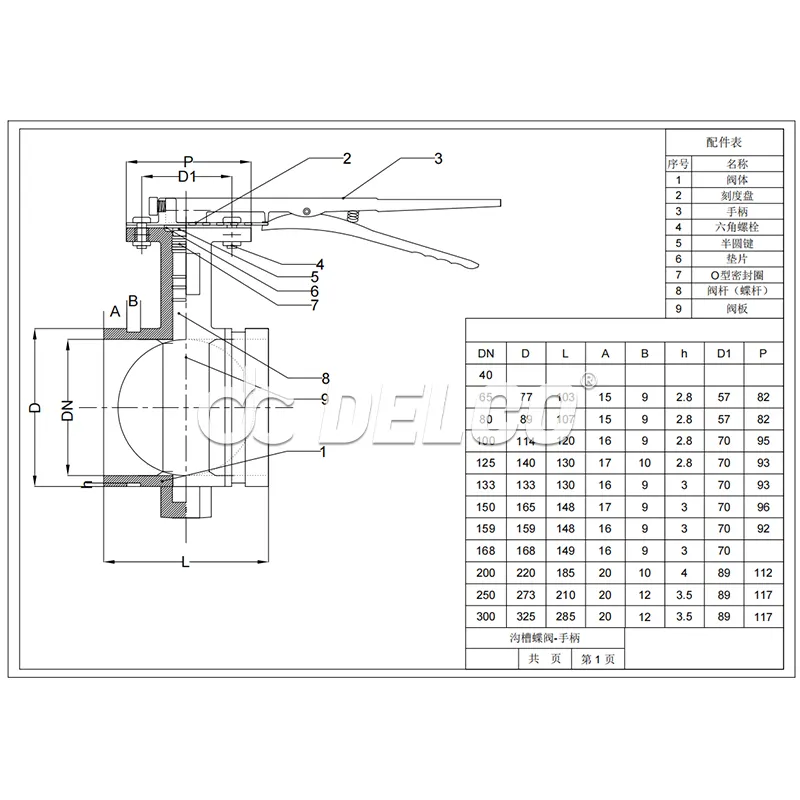
DELCO D81X-16 lever-operated grooved butterfly valve reference drawing. Confirm the applicable dimensions and tolerances against the drawing for the selected supply configuration.
Connection-End Dimensions
Start with the valve-end diameter and groove detail. Compare the physical features against the selected coupling’s requirements.
The relevant checks include the end diameter, gasket seating area, groove width, and groove diameter or other specified profile dimensions.
Check each drawing’s dimension definitions before comparing values. In the supplied DELCO drawing, D identifies an end diameter. Another technical document may use the same letter for a different feature.
A matching letter is not evidence of a matching dimension. Compare the feature, value, units, and tolerance together.
Valve End-to-End Length
The dimension marked L in the DELCO drawing spans the valve body from end to end.
For replacement work, compare this length with the existing valve and available pipe opening. Review the selected coupling’s assembly requirements, including any specified end separation.
A valve may have suitable connection ends yet still require pipework changes because its installation length differs from the original valve.
Complete Motorized Assembly
A lever-operated drawing does not show the overall dimensions of an electric valve assembly.
Request a drawing covering the selected valve, actuator, and mounting arrangement. Check:
- Overall height and width.
- Actuator orientation and bracket dimensions.
- Cable-entry access.
- Manual-override operating space.
- Clearance for coupling assembly and removal.
- Any required clearance for disc movement near adjacent components.
These checks are particularly important inside packaged equipment, existing pipe racks, and crowded plant rooms.
For the product enquiry, refer to DELCO Motorized Grooved Butterfly Valve and request the connection-end and motorized assembly drawings for the selected configuration.
4. Confirm Service Ratings and Seal Materials
Dimensional fit is only one part of grooved butterfly valve coupling compatibility. The connection must also be suitable for the intended medium, pressure, and temperature.
Provide the fluid, design pressure, operating temperature range, and any relevant additives or cleaning conditions.
Specify the valve seat and coupling gasket separately. An EPDM valve seat, for example, does not identify the gasket material or grade supplied with a separate coupling.
| Item | What Needs Confirmation |
|---|---|
| Valve body and internal components | Suitability for the medium and specified operating conditions |
| Valve seat | Material and applicable service limits |
| Coupling gasket | Manufacturer’s material grade and suitability for the fluid and temperature |
| Coupling and prepared pipe | Applicable rating for the selected size, pipe material, wall thickness, and end preparation |
| Complete connection | Suitability for the project’s design conditions |
Do not approve the complete joint from the valve’s pressure marking alone. Check the applicable requirements and limits of the proposed combination.
For fire-protection applications, confirm the required listings, approvals, and accepted configuration for the actual products being supplied. General suitability for water service does not establish project approval.
5. Check Coupling Arrangement and Electric Actuator Requirements
Rigid and flexible couplings serve different piping-design purposes. Select the arrangement according to the project design and the requirements of the chosen products.
For a motorized valve, review the valve and actuator weight, mounting orientation, operating loads, and support requirements. Using flexible couplings does not automatically provide the required support or accommodate every type of movement.
The electrical specification should describe the required operation clearly.
| Requirement | Information to Specify |
|---|---|
| Power supply | Voltage, AC or DC, and frequency where applicable |
| Control duty | On/off isolation or modulating control |
| Control input | Required command or control signal |
| Position feedback | Required status contacts or feedback signal |
| Operating time | Required opening and closing time |
| Installation environment | Indoor or outdoor location and required enclosure protection |
| Manual operation | Required manual-override access and function |
For broader selection considerations, see Electric Butterfly Valve Guide Features Types and Selection Tips. Use that guidance alongside the connection requirements for the chosen grooved model.
Also distinguish powered operation from electrical monitoring. A valve with a position-monitoring switch may still be operated manually. State explicitly whether the project requires powered opening and closing, position feedback, or both.
6. Decide Whether the Order Is Ready for Confirmation
Use the results of the review to identify the next action.
| Review Result | Next Action |
|---|---|
| Pipe OD or coupling model is unknown | Obtain the missing identification and specification before confirming the connection |
| Documents show different groove requirements | Select a compatible configuration or request an engineered connection solution |
| Dimensions appear suitable, but service ratings are unresolved | Complete the pressure, temperature, material, and gasket review |
| Connection details are confirmed, but motorized dimensions are missing | Obtain the complete assembly drawing before approving installation fit |
| Technical requirements and supply configuration are confirmed | Record the selected models, drawing revisions, and agreed conditions in the order |
Example: A replacement enquiry includes the existing coupling model and pipe specification, but only a lever-operated drawing for the proposed valve. The connection review can begin, but the installation-space review remains open until the selected electric actuator assembly is documented.
This approach keeps unresolved items visible and gives the buyer a clear basis for order confirmation.
7. Enquiry Checklist for a Motorized Grooved Butterfly Valve
Send the following information with your enquiry. Where a detail is unknown, identify it clearly and attach the available documents or photographs.
| Information to Provide | What to Include |
|---|---|
| Application and medium | System function, fluid, and relevant additives |
| Nominal size and actual pipe OD | DN or NPS designation plus specified OD and units |
| Pipe material and wall thickness | Material specification and thickness or schedule |
| Groove requirements | Applicable specification, required edition, or pipe-end drawing |
| Coupling identification | Manufacturer, model, size, and photographs of existing markings |
| Coupling gasket | Material or manufacturer’s grade, if known |
| Pressure and temperature | Design pressure and operating temperature range |
| Installation conditions | New installation or replacement, available space, and existing valve dimensions |
| Actuator requirements | Power supply, control mode, feedback, and enclosure requirements |
| Quantity and documentation | Quantity, required drawings, and project submittals |
Before releasing the order, request written confirmation identifying the selected configuration, applicable drawings, and agreed connection requirements.
Frequently Asked Questions
Possibly, but reuse requires a review of the exact coupling, proposed valve ends, operating conditions, and component condition. Follow the coupling manufacturer’s requirements for inspection, gasket replacement, and reassembly. Matching nominal size alone is insufficient.
Yes, in some cases. Compatibility must be confirmed for the specific models, sizes, and operating conditions. Compare the documented end geometry, groove requirements, service ratings, and gasket suitability, and obtain confirmation from the relevant suppliers before ordering.
Provide clear photographs of the coupling markings, the complete connection, and the surrounding installation. Include any pipe specifications, existing valve drawings, or maintenance records. Use those details to help identify the components before final selection.
Prepare Your DELCO Enquiry
Send your pipe OD, coupling identification, operating conditions, and actuator requirements with your DELCO enquiry.
For replacement projects, include the existing valve dimensions and photographs showing the connection and available space. Request the corresponding valve-end and motorized assembly drawings so the selected configuration can be checked before order confirmation.
Share on Social:


- PREV: Wafer Ball Valve vs Flanged Ball Valve: Fit Checks for Compact Skids
- NEXT: Not NEXT